Posts Tagged ‘копирам ic firmware’
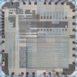
 Attack Chip PIC16F72 Heximal
Attack Chip PIC16F72 and extract content from memory out then copy the code to other blank microcontroller PIC16F72, the format of code will be Heximal;
Devices Included In This Data Sheet:
Low-Power Features:
· Standby Current:
– 40 nA @ 1.8V, typical
· Operating Current:
High-Performance RISC CPU when Attack Chip:
· Only 35 Instructions to Learn:
– All single-cycle instructions except branches
· Operating Speed:
– DC – 16 MHz oscillator/clock input
– DC – 250 ns instruction cycle
· Up to 4K x 14 Words of Flash Program Memory
· Up to 256 bytes of Data Memory (RAM)
· Interrupt Capability
· 8-Level Deep Hardware Stack
· Direct, Indirect and Relative Addressing modes if Attack Chip
· Processor Self-Write/Read access to Program Memory
Special Microcontroller Features:
· Precision Internal Oscillator:
– 16 MHz or 500 kHz operation
– Factory calibrated to ±1%, typical
– Software tunable
– Software selectable ÷1, ÷2, ÷4 or ÷8 divider
· Power-Saving Sleep mode
· Industrial and Extended Temperature Range before Attack Chip
· Power-on Reset (POR)
· Power-up Timer (PWRT)
· Brown-out Reset (BOR)
· Multiplexed Master Clear with Pull-up/Input Pin
· Programmable Code Protection
· In-Circuit Serial ProgrammingTM (ICSPTM) via Two Pins
· 128 Bytes High-Endurance Flash:
– 100,000 write Flash endurance (minimum) after Attack Chip
· Wide Operating Voltage Range:
– 1.8V to 5.5V (PIC16F720/721)
– 1.8V to 3.6V (PIC16LF720/721)
– 35 mA/MHz @ 1.8V, typical
· Low-Power Watchdog Timer Current:
– 500 nA @ 1.8V, typical
Peripheral Features:
· Up to 17 I/O Pins and 1 Input-only Pin:
– High-current source/sink for direct LED drive after Attack Chip
– Interrupt-on-change pins
– Individually programmable weak pull-ups
· A/D Converter:
– 8-bit resolution
– 12 channels
– Selectable Voltage reference
· Timer0: 8-Bit Timer/Counter with 8-Bit Programmable Prescaler
· Enhanced Timer1
– 16-bit timer/counter with prescaler
– External Gate Input mode with toggle and single shot modes for Attack Chip
– Interrupt-on-gate completion
· Timer2: 8-Bit Timer/Counter with 8-Bit Period Register, Prescaler and Postscaler
· Capture, Compare, PWM module (CCP)
– 16-bit Capture, max resolution 12.5 ns
– 16-bit Compare, max resolution 250 ns
– 10-bit PWM, max frequency 15 kHz
· Addressable Universal Synchronous
Asynchronous Receiver Transmitter (AUSART)
· Synchronous Serial Port (SSP)
– SPI (Master/Slave)
– I2CTM (Slave) with Address Mask when Attack Chip
