Posts Tagged ‘wiederherstellen Mikroprozessor eingebettete Firmware’
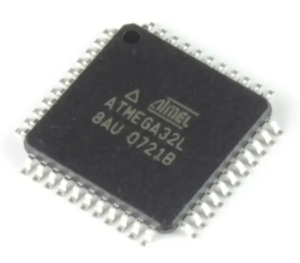
 Restoring ATmega32L Microprocessor Memory Software
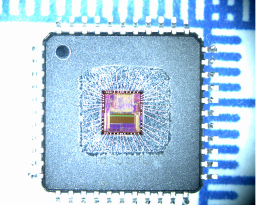
Restoring ATmega32L Microprocessor Memory Software in the format of heximal or binary, original memory data inside atmega32l mcu will be cloned and embedded firmware will be readout from atmega32l;

The EEPROM Write Enable Signal EEWE is the write strobe to the EEPROM. When address and data are correctly set up, the EEWE bit must be written to one to write the value into the EEPROM. The EEMWE bit must be written to one before a logical one is written to EEWE, otherwise no EEPROM write takes place. The following pro- cedure should be followed when writing the EEPROM (the order of steps 3 and 4 is not essential):
- Wait until EEWE becomes zero.
- Wait until SPMEN in SPMCR becomes zero.
- Write new EEPROM address to EEAR (optional).
- Write new EEPROM data to EEDR (optional).
- Write a logical one to the EEMWE bit while writing a zero to EEWE in EECR.
- Within four clock cycles after setting EEMWE, write a logical one to EEWE.
The EEPROM can not be programmed during a CPU write to the Flash memory. The software must check that the Flash programming is completed before initiating a new EEPROM write to reverse engineer atmega8a microchip memory. Step 2 is only relevant if the software con- tains a boot loader allowing the CPU to program the Flash.
If the Flash is never being updated by the CPU, step 2 can be omitted. See “Boot Loader Support – Read-While-Write Self-Programming” on page 201 for details about boot programming.
Caution: An interrupt between step 5 and step 6 will make the write cycle fail, since the EEPROM Master Write Enable will time-out. If an interrupt routine accessing the EEPROM is interrupting another EEPROM access.

restaurando o software de memória do microprocessador ATmega32L no formato de heximal ou binário, os dados de memória originais dentro do atmega32l mcu serão clonados e o firmware incorporado será lido a partir do atmega32
the EEAR or EEDR Register will be modified, causing the interrupted EEPROM access to fail. It is recommended to have the Global Interrupt Flag cleared during all the steps to avoid these problems.
When the write access time has elapsed, the EEWE bit is cleared by hardware in order to restore microcontroller atmega8l flash data. The user software can poll this bit and wait for a zero before writing the next byte. When EEWE has been set, the CPU is halted for two cycles before the next instruction is executed.
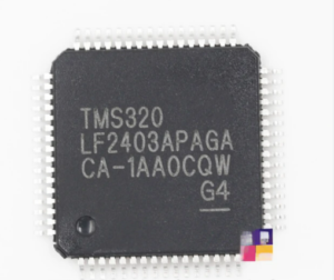
 Restore DSP TMS320LF2403 Microprocessor Memory Program
Restore DSP TMS320LF2403 Microprocessor Memory Program starts from unlocking tms320f240 cpu flash memory and copy embedded firmware to new microcontroller;

C2000™ 32-bit microcontrollers are optimized for processing, sensing, and actuation to improve closed- loop performance in real-time control applications such as industrial motor drives; solar inverters and digital power; electrical vehicles and transportation; motor control; and sensing and signal processing. The C2000 line includes the Premium performance MCUs and the Entry performance MCUs.
The F2806x family of microcontrollers (MCUs) provides the power of the C28x core and CLA coupled with highly integrated control peripherals in low pin-count devices. This family is code-compatible with previous C28x-based code, and also provides a high level of analog integration.

восстановление заблокированной флэш-памяти микропроцессора DSP TMS320LF2403 начинается с взлома защищенного TMS320LF2403 защищенного плавкого предохранителя микрокомпьютера и системы защиты от несанкционированного доступа, а затем копируется встроенная прошивка в двоичном или шестнадцатеричном формате в новый микроконтроллер;
An internal voltage regulator allows for single-rail operation. Enhancements have been made to the HRPWM module to allow for dual-edge control (frequency modulation). Analog comparators with internal 10-bit references have been added and can be routed directly to control the ePWM outputs when restoring tms320f28067 dsp mcu locked flash program.
The ADC converts from 0 to 3.3-V fixed full-scale range and supports ratio-metric VREFHI/VREFLO references. The ADC interface has been optimized for low overhead and latency.

Wiederherstellen des gesperrten DSP TMS320LF2403-Mikroprozessor-Flash-Speicherprogramms beginnt mit dem durch einen Riss gesicherten TMS320LF2403-gesicherten Mikrocomputer-Sicherungsbit und Manipulationsschutzsystem und anschließendes Kopieren der eingebetteten Firmware im Binär- oder Heximalformat auf den neuen Mikrocontroller;