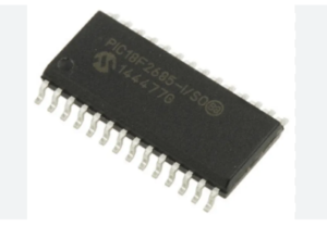
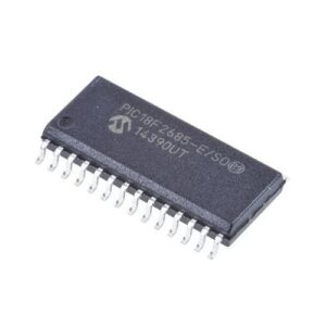
 Reverse PIC18F2685 MCU Eprom Code
Reverse engineering encrypted PIC18F2685 MCU eprom code is a process starts from unlock secured PIC18F2685 microcontroller protective system, retrieve protective embedded firmware content from PIC18F2685 microprocessor flash program memory and eeprom data memory in the format of binary code or heximal software;

Reverse engineering encrypted PIC18F2685 MCU eprom code is a process starts from unlock secured PIC18F2685 microcontroller protective system, retrieve protective embedded firmware content from PIC18F2685 microprocessor flash program memory and eeprom data memory in the format of binary code or heximal software
An exit from Sleep mode or any of the Idle modes is triggered by an interrupt from Crack MCU Program, a Reset or a WDT time-out. This section discusses the triggers that cause exits from power-managed modes from Reverse PIC18F2685 MCU Eprom Code. The clocking subsystem actions are discussed in each of the power-managed modes.
Any of the available interrupt sources can cause the device to exit from an Idle mode or the Sleep mode to a Run mode. To enable this functionality, an interrupt source must be enabled by setting its enable bit in one of the INTCON or PIE registers when Reverse Engineering MCU ATMEGA324PV heximal, The exit sequence is initiated when the corresponding interrupt flag bit is set.

L’ingénierie inverse du code EEPROM crypté du microcontrôleur PIC18F2685 est un processus qui commence par le déverrouillage du système de protection sécurisé du microcontrôleur PIC18F2685, la récupération du contenu du micrologiciel intégré de protection à partir de la mémoire de programme flash du microprocesseur PIC18F2685 et de la mémoire de données EEPROM au format de code binaire ou de logiciel hexadécimal ;
On all exits from Idle or Sleep modes by interrupt, code execution branches to the interrupt vector if the GIE/ GIEH bit (INTCON<7>) is set. Otherwise, code execution continues or resumes without branching.
A fixed delay of interval TCSD following the wake event is required when leaving Sleep and Idle modes. This delay is required for the CPU to prepare for execution after Recover MCU ATMEGA324A firmware. Instruction execution resumes on the first clock cycle following this delay.
A WDT time-out will cause different actions depending on which power-managed mode the device is in when the time-out occurs. If the device is not executing code (all Idle modes and Sleep mode), the time-out will result in an exit from the power-managed mode for the purpose of Break Microcontroller ATmega324PA binary, If the device is executing code from Reverse PIC18F2685 MCU Eprom Code (all Run modes), the time-out will result in a WDT Reset.

reverse engineering van gecodeerde PIC18F2685 MCU eprom-code is een proces dat begint met het ontgrendelen van het beveiligde PIC18F2685 microcontrollerbeveiligingssysteem, het ophalen van beschermende ingebedde firmware-inhoud uit het flashprogrammageheugen en eeprom-datageheugen van de PIC18F2685 microprocessor in de vorm van binaire code of heximale software;
The WDT timer and postscaler are cleared by executing a SLEEP or CLRWDT instruction, the loss of a currently selected clock source (if the Fail-Safe Clock Monitor is enabled) and modifying the IRCF bits in the OSCCON register from Break IC ATMEGA644 eeprom if the internal oscillator block is the device clock source.

