 Reverse Engineering Microcontroller ATmega644PA Firmware
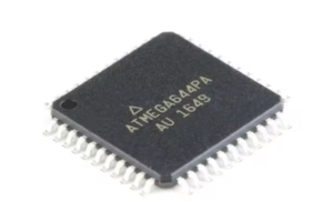
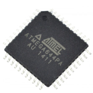
Reverse engineering Microcontroller ATmega644PA firmware involves decoding and analyzing the embedded firmware stored within its flash memory program. Engineers often seek to recover or clone this microcontroller’s source code for testing, replication, or troubleshooting purposes. The ATmega644PA, known for its robust design in embedded systems, stores critical program instructions as binary data in EEPROM and flash memory, ensuring reliable functionality.

Beim Reverse Engineering der Firmware des Mikrocontrollers ATmega644PA geht es um das Dekodieren und Analysieren der eingebetteten Firmware, die in seinem Flash-Speicherprogramm gespeichert ist. Ingenieure versuchen häufig, den Quellcode dieses Mikrocontrollers zu Test-, Replikations- oder Fehlerbehebungszwecken wiederherzustellen oder zu klonen. Der ATmega644PA, der für sein robustes Design in eingebetteten Systemen bekannt ist, speichert kritische Programmbefehle als Binärdaten im EEPROM und Flash-Speicher und gewährleistet so eine zuverlässige Funktionalität.
To break through security features protecting this firmware, reverse engineering techniques must be employed to decode the program into a readable heximal file. This file format allows engineers to analyze the binary data and reconstruct the original source code, providing insights into how the microcontroller operates under different conditions. Recovering and cloning the ATmega644PA’s firmware requires precision to avoid data corruption, particularly as accessing EEPROM memory data often triggers security locks.
By managing each stage of the reverse engineering process carefully, engineers can maintain the integrity of the microcontroller’s program, ensuring any recovered source code is accurate and reliable. This process can be essential for device maintenance, compatibility testing, or creating compatible hardware designs that rely on the ATmega644PA’s core functions.
Note that if a level triggered interrupt is used for wake-up from Power-down mode, the changed level must be held for some time to wake up the procedures of Reverse Engineering Microcontroller ATmega644PA Firmware.
Refer to “External Interrupts”. When waking up from Power-down mode, there is a delay from the wake-up condition occurs until the wake-up becomes effective by Recover IC ST62T65C6 Software. This allows the clock to restart and become stable after having been stopped.

रिवर्स इंजीनियरिंग माइक्रोकंट्रोलर ATmega644PA फर्मवेयर में इसके फ्लैश मेमोरी प्रोग्राम में संग्रहीत एम्बेडेड फर्मवेयर को डिकोड करना और उसका विश्लेषण करना शामिल है। इंजीनियर अक्सर परीक्षण, प्रतिकृति या समस्या निवारण उद्देश्यों के लिए इस माइक्रोकंट्रोलर के स्रोत कोड को पुनर्प्राप्त या क्लोन करना चाहते हैं। एम्बेडेड सिस्टम में अपने मजबूत डिजाइन के लिए जाना जाने वाला ATmega644PA, महत्वपूर्ण प्रोग्राम निर्देशों को EEPROM और फ्लैश मेमोरी में बाइनरी डेटा के रूप में संग्रहीत करता है, जिससे विश्वसनीय कार्यक्षमता सुनिश्चित होती है।
The wake-up period is defined by the same CKSEL Fuses that define the Reset Time-out period, as described in “Clock Sources” on page 40. When the SM2..0 bits are written to 011, the SLEEP instruction makes the MCU Cracking enter Power-save mode.
This mode is identical to Power-down, with one exception: If Timer/Counter2 is enabled, it will keep running during sleep. The device can wake up from either Timer Overflow or Output Compare event from Timer/Counter2 if the corresponding Timer/Counter2 interrupt enable bits are set in TIMSK2 to facilitate the process of Attack MCU MSP430G2452IPW14R Heximal, and the Global Interrupt Enable bit in SREG is set.
If Timer/Counter2 is not running, Power-down mode is recommended instead of Power-save mode. The Timer/Counter2 can be clocked both synchronously and asynchronously in Power-save mode. If the Timer/Counter2 is not using the asynchronous clock, the Timer/Counter Oscillator is stopped during sleep.

سیستم عامل میکروکنترلر ATmega644PA مهندسی معکوس شامل رمزگشایی و تجزیه و تحلیل سیستم عامل تعبیه شده ذخیره شده در برنامه حافظه فلش خود است. مهندسان اغلب به دنبال بازیابی یا شبیه سازی کد منبع این میکروکنترلر برای اهداف آزمایش، تکرار یا عیب یابی هستند. ATmega644PA که به دلیل طراحی قوی خود در سیستمهای تعبیهشده شناخته میشود، دستورالعملهای برنامه حیاتی را به عنوان دادههای باینری در EEPROM و حافظه فلش ذخیره میکند و از عملکرد قابل اعتماد اطمینان میدهد.
If the Timer/Counter2 is not using the synchronous clock, the clock source is stopped during sleep. Note that even if the synchronous clock is running in Power-save, this clock is only available for the Timer/Counter2 in order to Attack IC TMS320F28232PGFA Software.
When the SM2..0 bits are 110 and an external crystal/resonator clock option is selected, the SLEEP instruction makes the MCU enter Standby mode. This mode is identical to Power-down with the exception that the Oscillator is kept running. From Standby mode, the device wakes up in six clock cycles.
