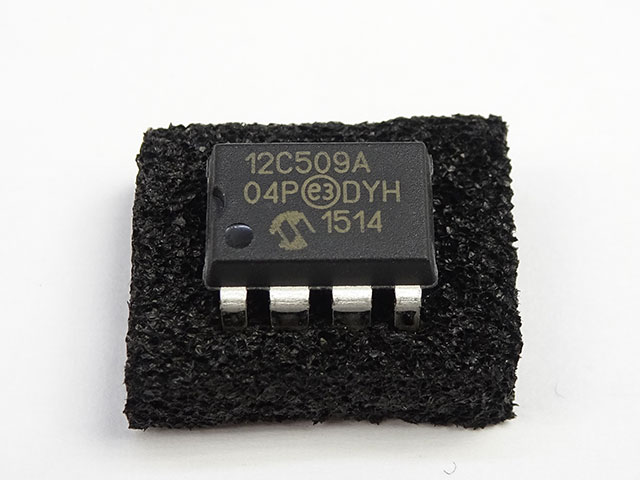
 Recover MCU PIC12CR509A Flash
the PIC12CR509A microcontroller is widely used for its efficiency and compact design. However, many of these MCUs come with secured or locked firmware, making it challenging to access their flash memory or EEPROM data. This is where professional MCU crack services come into play, offering solutions to recover, decrypt, and extract critical information from protected chips.
Le microcontrôleur PIC12CR509A est largement utilisé pour son efficacité et sa conception compacte. Cependant, bon nombre de ces microcontrôleurs sont livrés avec un micrologiciel sécurisé ou verrouillé, ce qui rend difficile l’accès à leur mémoire flash ou à leurs données EEPROM. C’est là qu’interviennent les services professionnels de crackage de microcontrôleurs, proposant des solutions pour récupérer, décrypter et extraire des informations critiques à partir de puces protégées.
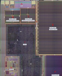
Using advanced techniques such as reverse engineering and binary analysis, experts can unlock the encrypted firmware of the PIC12CR509A. Whether the goal is to decode the source code, dump the flash memory, or replicate the program for further development, these services provide a pathway to bypass the secured barriers. By employing non-invasive methods, the original chip remains intact while the protected data is extracted.
역엔지니어링 및 바이너리 분석과 같은 고급 기술을 사용하여 전문가는 PIC12CR509A의 암호화된 펌웨어를 잠금 해제할 수 있습니다. 소스 코드를 디코딩하거나, 플래시 메모리를 덤프하거나, 추가 개발을 위해 프로그램을 복제하는 것이 목표이든, 이러한 서비스는 보안 장벽을 우회하는 경로를 제공합니다. 비침습적 방법을 사용함으로써 보호된 데이터가 추출되는 동안 원래 칩은 그대로 유지됩니다.
For those looking to hack or break into a locked MCU, specialized tools and software are used to attack the encryption algorithms. This process often involves decoding the binary files, analyzing the memory structure, and reconstructing the original firmware archive. Such services are invaluable for recovering lost data, cloning microcontrollers, or understanding the functionality of a protected microprocessor.
लॉक किए गए MCU को हैक करने या उसमें सेंध लगाने की चाहत रखने वालों के लिए, एन्क्रिप्शन एल्गोरिदम पर हमला करने के लिए विशेष उपकरण और सॉफ़्टवेयर का उपयोग किया जाता है। इस प्रक्रिया में अक्सर बाइनरी फ़ाइलों को डिकोड करना, मेमोरी संरचना का विश्लेषण करना और मूल फ़र्मवेयर संग्रह का पुनर्निर्माण करना शामिल होता है। ऐसी सेवाएँ खोए हुए डेटा को पुनर्प्राप्त करने, माइक्रोकंट्रोलर को क्लोन करने या संरक्षित माइक्रोप्रोसेसर की कार्यक्षमता को समझने के लिए अमूल्य हैं।
However, it’s important to note that MCU crack services should only be used for legitimate purposes, such as recovering data from a damaged chip or reverse engineering for compatibility improvements. With the right expertise, even the most secured PIC12CR509A flash memory can be unlocked, providing access to its hidden treasures.
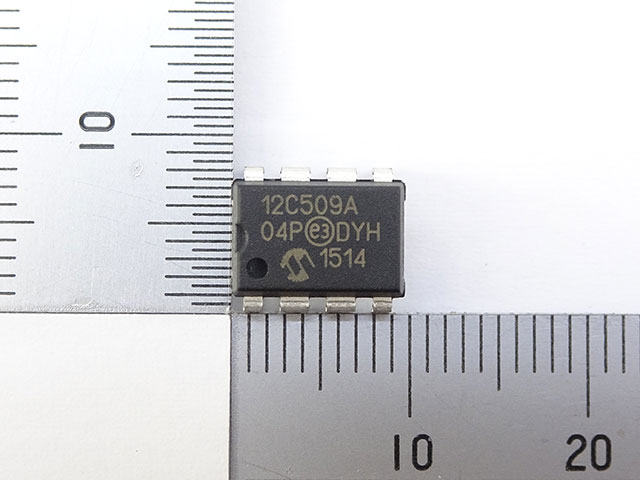
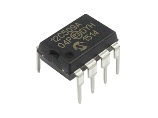
We can Recover MCU PIC12CR509A Flash, please view the MCU PIC12CR509A features for your reference:
The PICCR509A each have 16 bytes of EEPROM data memory. The EEPROM memory has an endurance of 1,000,000 erase/write cycles and a data retention of greater than 40 years. The EEPROM data memory supports a bi-directional 2-wire bus and data transmission protocol.
These two-wires are serial data (SDA) and serial clock (SCL), that are mapped to bit6 and bit7, respectively, of the GPIO register (SFR 06h). Unlike the GP0-GP5 that are connected to the I/O pins, SDA and SCL are only connected to the internal EEPROM peripheral in order to Break IC PIC12F639 Heximal. For most applications, all that is required is calls to the following functions:
The code for these functions is available on our website www.microchip.com. The code will be accessed by either including the source code FL51XINC.ASM or by linking FLASH5IX.ASM. It is very important to check the return codes when using these calls, and retry the operation if unsuccessful.
Recover MCU PIC12CR509A Flash
Unsuccessful return codes occur when the EE data memory is busy with the previous write, which can take up to 4 mS. SDA is a bi-directional pin used to transfer addresses and data into and data out of the device before Recover MCU.
For normal data transfer SDA is allowed to change only during SCL low. Changes during SCL high are reserved for indicating the START and STOP conditions. The EEPROM interface is a 2-wire bus protocol consisting of data (SDA) and a clock (SCL) when Recover MCU PIC12CR509A Flash.
Although these lines are mapped into the GPIO register, they are not accessible as external pins; only to the i internal EEPROM peripheral. SDA and SCL operation is also slightly different than GPO-GP5 as listed below. Namely, to avoid code overhead in modifying the TRIS register to complete the process of Break IC PIC12F615 Software, both SDA and SCL are always outputs.
To read data from the EEPROM peripheral requires outputting a ‘1’ on SDA placing it in high-Z state, where only the internal 100K pull-up is active on the SDA line. SDA:
Built-in 100K (typical) pull-up to VDD Open-drain (pull-down only)
Always an output
Outputs a ‘1’ on reset
SCL:
Full CMOS output
Always an output
Outputs a ‘1’ on reset
The following example requires:
· Code Space: 77 words
· RAM Space: 5 bytes (4 are overlayable)
· Stack Levels:1 (The call to the function itself. The functions do not call any lower level functions.)
· Timing:
– WRITE_BYTE takes 328 cycles
– READ_CURRENT takes 212 cycles
– READ_RANDOM takes 416 cycles.
· IO Pins: 0 (No external IO pins are used)
This code must reside in the lower half of a page. The code achieves it’s small size without additional calls through the use of a sequencing table to Crack MCU. The table is a list of procedures that must be called in order. The table uses an ADDWF PCL,F instruction, effectively a computed goto, to sequence to the next procedure. However the ADDWF PCL,F instruction yields an 8 bit address, forcing the code to reside in the first 256 addresses of a page.