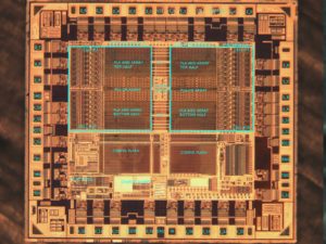
 Recover MCU ATMEGA162A Heximal
Recovering MCU ATMEGA162A heximal data is a meticulous process involving advanced techniques to decode and restore the embedded firmware stored within this microcontroller’s flash memory program. This task may arise when source code or program data becomes corrupted, lost, or requires duplication for compatible systems. The ATMEGA162A MCU, known for its reliability in embedded applications, stores critical information in binary format within its EEPROM and flash memory.
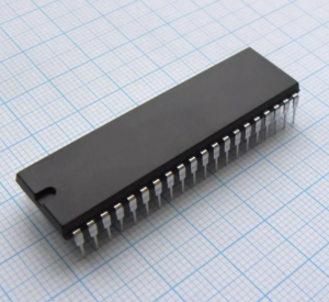
recovering MCU ATMEGA162A heximal data is a meticulous process involving advanced techniques to decode and restore the embedded firmware stored within this microcontroller’s flash memory program. This task may arise when source code or program data becomes corrupted, lost, or requires duplication for compatible systems. The ATMEGA162A MCU, known for its reliability in embedded applications, stores critical information in binary format within its EEPROM and flash memory
To recover the heximal file, reverse engineering tools are often used to break the security layers protecting the firmware. This process involves decoding the binary data and converting it into a heximal file that represents the original source code. By reconstructing the code, engineers can clone or duplicate the program for testing, troubleshooting, or system recovery purposes. However, any attempt to access EEPROM memory data must be done cautiously to avoid corrupting the firmware, as the ATMEGA162A’s security features are designed to prevent unauthorized access.
Successfully recovering MCU ATMEGA162A heximal data allows for precise replication of the original firmware, enabling continued use or adaptation of the program across various hardware setups. This approach is essential for maintaining system reliability and ensuring compatibility in embedded applications.
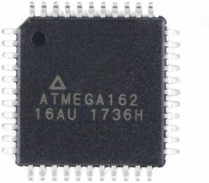
بازیابی دادههای هگزیمال MCU ATMEGA162A یک فرآیند دقیق شامل تکنیکهای پیشرفته برای رمزگشایی و بازیابی میانافزار تعبیهشده ذخیرهشده در برنامه حافظه فلش این میکروکنترلر است. این کار ممکن است زمانی ایجاد شود که کد منبع یا داده های برنامه خراب شود، از بین برود یا برای سیستم های سازگار نیاز به تکرار داشته باشد. ATMEGA162A MCU، که به خاطر قابلیت اطمینان خود در برنامه های جاسازی شده معروف است، اطلاعات حیاتی را در قالب باینری در EEPROM و حافظه فلش خود ذخیره می کند.
When the SM2..0 bits are 111 and an external crystal/resonator clock option is selected, the SLEEP instruction makes the MCU Cracking enter Extended Standby mode. This mode is identical to Power-save mode with the exception that the Oscillator is kept running.
From Extended Standby mode, the device wakes up in six clock cycles. The Power Reduction Register, PRR, provides a method to stop the clock to individual peripherals to reduce power consumption. The current state of the peripheral is frozen and the I/O registers can not be read or written in the process of Recover MCU heximal.
Resources used by the peripheral when stopping the clock will remain occupied, hence the peripheral should in most cases be disabled before stopping the clock. Waking up a module, which is done by clearing the bit in PRR, puts the module in the same state as before shutdown.
Module shutdown can be used in Idle mode and Active mode to significantly reduce the overall power consumption. See “Supply Current of IO modules” on page 381 for examples. In all other sleep modes, the clock is already stopped.
Bit 7 – PRTWI: Power Reduction TWI
Writing a logic one to this bit shuts down the TWI by stopping the clock to the module. When waking up the TWI again, the TWI should be re initialized to ensure proper operation when recover MCU heximal.
Bit 6 – PRTIM2: Power Reduction Timer/Counter2
Writing a logic one to this bit shuts down the Timer/Counter2 module in synchronous mode (AS2 is 0). When the Timer/Counter2 is enabled, operation will continue like before the shutdown.
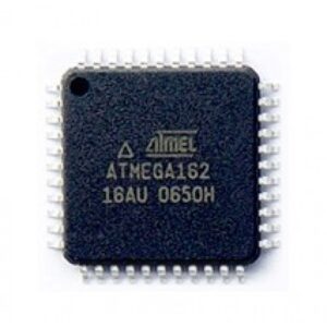
Die Wiederherstellung von MCU ATMEGA162A-Heximaldaten ist ein sorgfältiger Prozess, der fortschrittliche Techniken zum Dekodieren und Wiederherstellen der eingebetteten Firmware umfasst, die im Flash-Speicherprogramm dieses Mikrocontrollers gespeichert ist. Diese Aufgabe kann auftreten, wenn Quellcode oder Programmdaten beschädigt werden oder verloren gehen oder für kompatible Systeme dupliziert werden müssen. Die ATMEGA162A-MCU, die für ihre Zuverlässigkeit in eingebetteten Anwendungen bekannt ist, speichert kritische Informationen im Binärformat in ihrem EEPROM und Flash-Speicher.
Bit 5 – PRTIM0: Power Reduction Timer/Counter0
Writing a logic one to this bit shuts down the Timer/Counter0 module. When the Timer/Counter0 is enabled, operation will continue like before the shutdown.
Bit 4 – Res: Reserved bit
This bit is reserved bit and will always read as zero.
Bit 3 – PRTIM1: Power Reduction Timer/Counter1
Writing a logic one to this bit shuts down the Timer/Counter1 module. When the Timer/Counter1 is enabled, operation will continue like before the shutdown.
Bit 2 – PRSPI: Power Reduction Serial Peripheral Interface
Writing a logic one to this bit shuts down the Serial Peripheral Interface by stopping the clock to the module. When waking up the SPI again, the SPI should be re initialized to ensure proper operation after Break Chip Atmel Atmega48PV Heximal.
Bit 1 – PRUSART0: Power Reduction USART0
Writing a logic one to this bit shuts down the USART0 by stopping the clock to the module. When waking up the USART0 again, the USART0 should be re initialized to ensure proper operation.
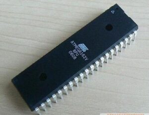
MCU ATMEGA162A हेक्सिमल डेटा को पुनर्प्राप्त करना एक सावधानीपूर्वक प्रक्रिया है जिसमें इस माइक्रोकंट्रोलर के फ्लैश मेमोरी प्रोग्राम में संग्रहीत एम्बेडेड फ़र्मवेयर को डिकोड और पुनर्स्थापित करने के लिए उन्नत तकनीकें शामिल हैं। यह कार्य तब हो सकता है जब स्रोत कोड या प्रोग्राम डेटा दूषित हो जाता है, खो जाता है, या संगत सिस्टम के लिए दोहराव की आवश्यकता होती है। ATMEGA162A MCU, एम्बेडेड अनुप्रयोगों में अपनी विश्वसनीयता के लिए जाना जाता है, अपने EEPROM और फ्लैश मेमोरी के भीतर बाइनरी प्रारूप में महत्वपूर्ण जानकारी संग्रहीत करता है
