 Microcontroller PIC18F2439 Code Reverse Engineering
Microcontroller PIC18F2439 Code Reverse Engineering can help designer to copy source code from original Microchip locked MCU PIC18F2439 in the format of binary file or heximal data through unlock secured microprocessor PIC18F2439 fuse bit and readout embedded firmware from flash program memory and eeprom software memory;
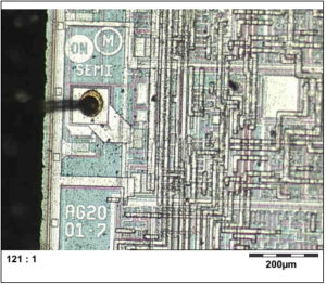
microcontroller PIC18F2439 code reverse engineering can help designer to copy source code from original Microchip locked MCU PIC18F2439 in the format of binary file or heximal data through unlock secured microprocessor PIC18F2439 fuse bit and readout embedded firmware from flash program memory and eeprom software memory;
PIC18LF2439 devices can be operated in ten different oscillator modes when Clone IC flash. The user can program the Configuration bits which can be obtained in the process of Microcontroller PIC18F2439 Code Reverse Engineering, FOSC3:FOSC0, in Configuration Register 1H to select one of these ten modes:
1. LP Low-Power Crystal
2. XT Crystal/Resonator
3. HS High-Speed Crystal/Resonator
4. HSPLL High-Speed Crystal/Resonator with PLL Enabled
5. RC External Resistor/Capacitor with FOSC/4 Output on RA6
6. RCIO External Resistor/Capacitor with I/O on RA6
7. INTIO1 Internal Oscillator with FOSC/4 Output on RA6 and I/O on RA7
8. INTIO2 Internal Oscillator with I/O on RA6 and RA7
9. EC External Clock with FOSC/4 Output
10. ECIO External Clock with I/O on RA6

माइक्रोकंट्रोलर PIC18F2439 कोड रिवर्स इंजीनियरिंग डिजाइनर को मूल माइक्रोचिप लॉक किए गए MCU PIC18F2439 से बाइनरी फ़ाइल या हेक्सिमल डेटा के प्रारूप में अनलॉक सुरक्षित माइक्रोप्रोसेसर PIC18F2439 फ्यूज बिट और फ्लैश प्रोग्राम मेमोरी और ईप्रोम सॉफ्टवेयर मेमोरी से एम्बेडेड फर्मवेयर रीडआउट के माध्यम से स्रोत कोड की प्रतिलिपि बनाने में मदद कर सकता है;
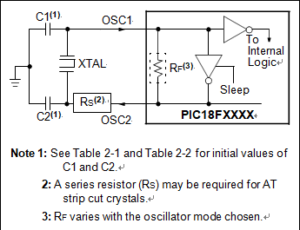
In XT, LP, HS or HSPLL Oscillator modes, a crystal or ceramic resonator is connected to the OSC1 and OSC2 pins to establish oscillation when Winbond Microcontroller W78E0516 Embedded Binary Recovering. Below Figure shows the pin connections.
The oscillator design requires the use of a parallel cut crystal. Different capacitor values may be required to produce acceptable oscillator operation after Reverse Engineering W78E52B Chip Data. The user should test the performance of the oscillator over the expected VDD and temperature range for the application.
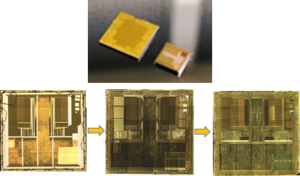
Обратный инжиниринг кода микроконтроллера PIC18F2439 может помочь разработчику скопировать исходный код с оригинального заблокированного микроконтроллера Microchip PIC18F2439 в формате двоичного файла или шестнадцатеричных данных с помощью разблокированного защищенного бита предохранителя микропроцессора PIC18F2439 и считывания встроенной прошивки из программной флэш-памяти и программной памяти EEPROM;
When using resonators with frequencies above 3.6 MHz, the use of HS mode, rather than XT mode, is recommended for the purpose of Attack Winbond W78E051A Protected Eeprom. HS mode may be used at any VDD for which the controller is rated. If HS is selected, it is possible that the gain of the oscillator will overdrive the resonator in order to Break Nuvoton W78E054 MCU Flash Memory. Therefore, a series resistor should be placed between the OSC2 pin and the resonator. As a good starting point, the recommended value of RS is 330Ù.
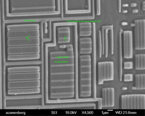
مهندسی معکوس کد میکروکنترلر PIC18F2439 می تواند به طراح کمک کند تا کد منبع را از MCU PIC18F2439 قفل شده با ریزتراشه اصلی در قالب فایل باینری یا داده هگزیمال از طریق باز کردن قفل ریزپردازنده ایمن PIC18F2439 و بازخوانی سیستم عامل تعبیه شده از حافظه نرم افزار فلش و e.p.
