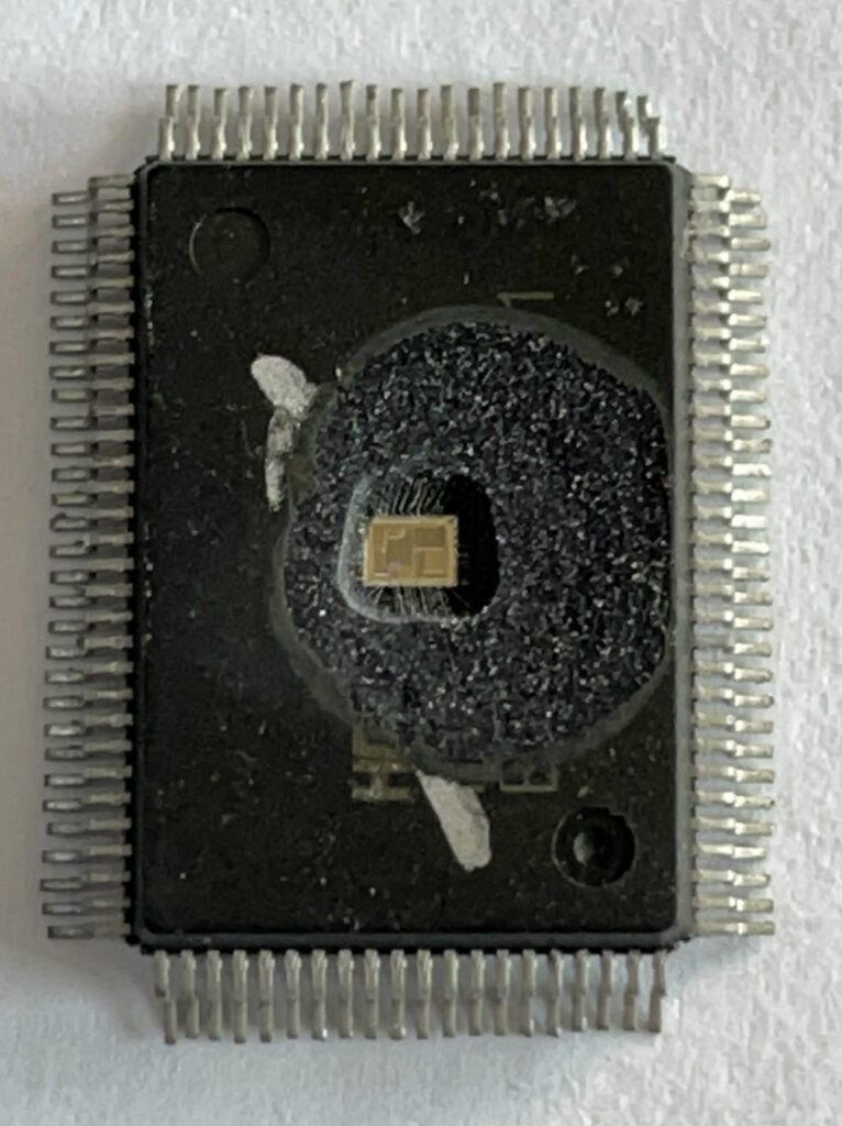
 Decode ST CPU ST72F321R9 Processor Locked Memory File
Decode ST CPU ST72F321R9 Processor Locked Memory File needs to use laser cutting to remove the security fuse bit of microcontroller, and then copy embedded flash firmware from mcu st72f321r9;

The Flash memory is organised in sectors and can be used for both code and data storage.
Depending on the overall Flash memory size in the micro-controller device, there are up to three user sectors (see below Table). Each of these sectors can be erased independently to avoid unnecessary erasing of the whole Flash memory when only a partial erasing is required after breaking st72f32ak1 mcu flash memory protection.

The first two sectors have a fixed size of 4 Kbytes (see below Figure). They are mapped in the upper part of the ST7 addressing space so the reset and in- terrupt vectors are located in Sector 0 (F000h- FFFFh).

3.5.1 Power supply schemes
- VDD = 2.4 to 3.6 V: external power supply for I/Os and the internal regulator. Provided externally through VDD pins.
- VDDA = from VDD to 3.6 V: external analog power supply for ADC, Reset blocks, RCs and PLL. The VDDA voltage level must be always greater or equal to the VDD voltage level and must be provided first.