Archive for the ‘Recover Chip’ Category
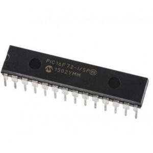
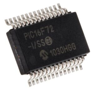
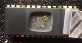
 Recover MCU PIC16F72A Firmware
Recover MCU PIC16F72A Firmware in the format of binary or heximal, reset the configurate bits of Microcontroller PIC16F72A from locked to open one by crack microcontroller fuse bit, then readout code from MCU;
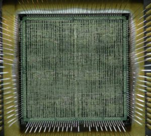
Recover MCU PIC16F72A Firmware in the format of binary or heximal, reset the configurate bits of Microcontroller PIC16F72A from locked to open one by crack microcontroller fuse bit, then readout code from MCU
This document contains device specific information for the operation of the PIC16F72 device. Additional information may be found in the PIC™ Mid-Range MCU Reference Manual (DS33023), which may be downloaded from the Microchip website. The Reference Manual should be considered a complementary document to this data sheet, and is highly recommended reading for a better understanding of the device architecture and operation of the peripheral modules.
The PIC16F72 belongs to the Mid-Range family of the PIC devices. The program memory contains 2K words, which translate to 2048 instructions, since each 14-bit program memory word is the same width as each device instruction. The data memory (RAM) contains 128 bytes after recover mcu AT89C4051 heximal.
There are 22 I/O pins that are user configurable on a pin-to-pin basis. Some pins are multiplexed with other device functions. These functions include:
· External interrupt
· Change on PORTB interrupt
· Timer0 clock input
· Timer1 clock/oscillator
· Capture/Compare/PWM
· A/D converter
· SPI/I2C
Table 1-1 details the pinout of the device with descriptions and details for each pin.
There are two memory blocks in the PIC16F72 device. These are the program memory and the data memory. Each block has separate buses so that concurrent access can occur. Program memory and data memory are explained in this section. Program memory can be read internally by the user code (see Section 7.0).
The data memory can further be broken down into the general purpose RAM and the Special Function Registers (SFRs). The operation of the SFRs that control the “core” are described here. The SFRs used to control the peripheral modules are described in the section discussing each individual peripheral module.
Additional information on device memory may be found in the PIC™ Mid-Range Reference Manual, (DS33023).
PIC16F72 devices have a 13-bit program counter capable of addressing a 8K x 14 program memory space.
The address range for this program memory is 0000h 07FFh. Accessing a location above the physically implemented address will cause a wraparound.
The RESET Vector is at 0000h and the Interrupt Vector is at 0004h.
The Data Memory is partitioned into multiple banks that contain the General Purpose Registers and the Special Function Registers. Bits RP1 (STATUS<6>) and RP0 (STATUS<5>) are the bank select bits.
 Recover MCU PIC16C63A Software
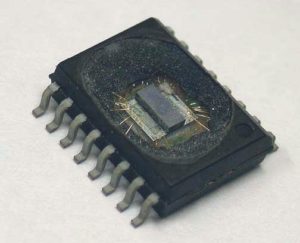
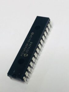
Recover MCU PIC16C63A software from Microcontroller PIC16C63A flash memory, the status of microprocessor PIC16C63A can be reset from locked to unlocked one by MCU cracking technology;
PIC16CXX Microcontroller Core Features:
· High performance RISC CPU
· Only 35 single word instructions to learn
· All single cycle instructions except for program branches which are two cycle
· Operating speed: DC – 20 MHz clock input DC – 200 ns instruction cycle
· 4 K x 14 words of Program Memory, 192 x 8 bytes of Data Memory (RAM)
· Interrupt capability
· Eight-level deep hardware stack
· Direct, indirect and relative addressing modes
· Power-on Reset (POR)
· Power-up Timer (PWRT) and Oscillator Start-up Timer (OST)
· Watchdog Timer (WDT) with its own on-chip RC oscillator for reliable operation
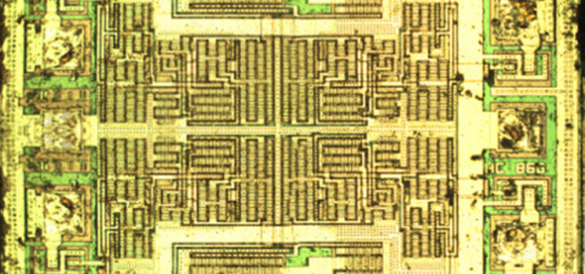
· Programmable code protection against mcu pic16c63a memory data unlocking
· Power-saving SLEEP mode crystal/clock
· Timer2: 8-bit timer/counter with 8-bit period register, prescaler and postscaler
· Capture, Compare, PWM modules
– Capture is 16-bit, max. resolution is 200 ns
– Compare is 16-bit, max. resolution is 200 ns
– PWM max. resolution is 10-bit
· 8-bit multichannel Analog-to-Digital converter
· Synchronous Serial Port (SSP) with SPITM and I2CTM
· Universal Synchronous Asynchronous Receiver Transmitter (USART/SCI)
· Parallel Slave Port (PSP), 8-bits wide with external RD, WR and CS controls
· Brown-out detection circuitry for Brown-out Reset (BOR)
· Selectable oscillator options
· Low power, high speed CMOS EPROM technology
· Wide operating voltage range: 2.5V to 5.5V
· High Sink/Source Current 25/25 mA
· Commercial, Industrial and Automotive temperature ranges
· Low power consumption:
– < 5 mA @ 5V, 4 MHz
– 23 µA typical @ 3V, 32 kHz
– < 1.2 µA typical standby current
 Recover IC PIC16C73B Firmware
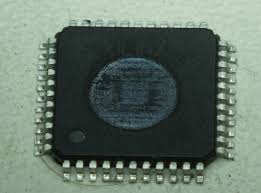
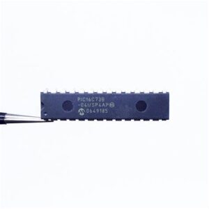
Recover IC PIC16C73B Firmware from MCU PIC16C73B flash memory, reset the status of microcontroller from locked to open by crack Microcontroller security fuse bit;
A highly reliable Watchdog Timer (WDT), with its own on-ic RC oscillator, provides protection against software lockup, and also provides one way of waking the device from SLEEP.
A UV erasable CERDIP packaged version is ideal for code development, while the cost effective One-Time-Programmable (OTP) version is suitable for production in any volume.
The PIC16C73B devices fit nicely in many applications ranging from security and remote sensors to appliance control and automotive. The EPROM technology makes customization of application programs (transmitter codes, motor speeds, receiver frequencies, etc.) extremely fast and convenient after Crack mcu pic16c73b flash and eeprom memory, readout embedded program/data from them.
The small footprint packages make this microcontroller series perfect for all applications with space limitations. Low cost, low power, high performance, ease of use and I/O flexibility make the PIC16C65B devices very versatile, even in areas where no microcontroller use has been considered before (e.g., timer functions, serial communication, capture and compare, PWM functions and coprocessor applications).
Users familiar with the PIC16C5X microcontroller family will realize that this is an enhanced version of the PIC16C5X architecture. Please refer to Appendix A for a detailed list of enhancements. Code written for the PIC16C5X can be easily ported to the PIC16CXX family of devices (Appendix B).
PICmicrochip® devices are supported by the complete line of Microchip Development tools. Please refer to Section 15.0 for more details about Microchip’s development tools.
A variety of frequency ranges and packaging options are available. Depending on application and production requirements, the proper device option can be selected using the information in the PIC16C63A/65B/73B/74B Product Identification System section at the end of this data sheet when Reading mcu pic16c73b eeprom memory content. When placing orders, please use that page of the data sheet to specify the correct part number.
For the PIC16C7X family, there are two device “types” as indicated in the device number.
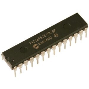
 Recover IC PIC16F873 Heximal
Recover IC PIC16F873 Heximal out from Microcontroller PIC16F873 secured memory, remove the protection over MCU PIC16F873 by Unlocking microcontroller security fuse bit, and readout the firmware from MCU flash memory;
Devices Included in this Data Sheet:
Analog Features:
· 10-bit, up to 8-channel Analog-to-Digital Converter (A/D)
· Brown-out Reset (BOR)
High-Performance RISC CPU:
· Only 35 single-word instructions to learn
· All single-cycle instructions except for program branches, which are two-cycle
· Operating speed: DC – 20 MHz clock input DC – 200 ns instruction cycle
· Up to 8K x 14 words of Flash Program Memory,
Up to 368 x 8 bytes of Data Memory (RAM),
Up to 256 x 8 bytes of EEPROM Data Memory
· Pinout compatible to other 28-pin or 40/44-pin PIC16CXXX and PIC16FXXX microcontrollers
Peripheral Features:
· Timer0: 8-bit timer/counter with 8-bit prescaler
· Timer1: 16-bit timer/counter with prescaler, can be incremented during Sleep via external crystal/clock
· Timer2: 8-bit timer/counter with 8-bit period register, prescaler and postscaler
· Two Capture, Compare, PWM modules
– Capture is 16-bit, max. resolution is 12.5 ns
– Compare is 16-bit, max. resolution is 200 ns
– PWM max. resolution is 10-bit
· Synchronous Serial Port (SSP) with SPI™ (Master mode) and I2C™ (Master/Slave)
· Universal Synchronous Asynchronous Receiver Transmitter (USART/SCI) with 9-bit address detection
· Parallel Slave Port (PSP) – 8 bits wide with external RD, WR and CS controls (40/44-pin only)
· Brown-out detection circuitry for Brown-out Reset (BOR)
· Analog Comparator module with:
– Two analog comparators
– Programmable on-chip voltage reference (VREF) module
– Programmable input multiplexing from device inputs and internal voltage reference
– Comparator outputs are externally accessible
Special Microcontroller Features:
· 100,000 erase/write cycle Enhanced Flash program memory typical
· 1,000,000 erase/write cycle Data EEPROM memory typical
· Data EEPROM Retention > 40 years
· Self-reprogrammable under software control
· In-Circuit Serial Programming™ (ICSP™) via two pins
· Single-supply 5V In-Circuit Serial Programming
· Watchdog Timer (WDT) with its own on-chip RC oscillator for reliable operation
· Programmable code protection
· Power saving Sleep mode
· Selectable oscillator options
· In-Circuit Debug (ICD) via two pins CMOS Technology:
· Low-power, high-speed Flash/EEPROM technology
· Fully static design
· Wide operating voltage range (2.0V to 5.5V)
· Commercial and Industrial temperature ranges
· Low-power consumption
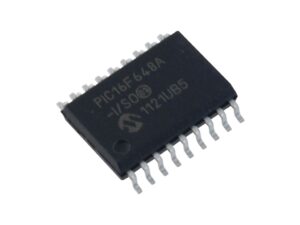
 Recover MCU PIC16F648A Firmware
Recover MCU PIC16F648A Firmware from microcontroller PIC16F648A flash memory is the result of MCU cracking, after application of this technique over the master MCU PIC16F648A with original program into it;
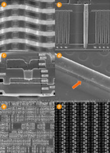
Recover MCU PIC16F648A Firmware from microcontroller PIC16F648A flash memory is the result of MCU cracking, after application of this technique over the master MCU PIC16F648A with original program into it
A variety of frequency ranges and packaging options are available. Depending on application and production requirements, the proper device option can be selected using the information in the PIC16F648A Product Identification System, at the end of this data sheet. When placing orders, please use this page of the data sheet to specify the correct part number.
FLASH Devices
FLASH devices can be erased and re-programmed electrically. This allows the same device to be used for prototype development, pilot programs and production. A further advantage of the electrically erasable FLASH is that it can be erased and reprogrammed in-circuit, or by device programmers, such as Microchip’s PICSTART® Plus, or PRO MATE® II programmers.
Quick-Turnaround-Production
(QTP) Devices Microchip offers a QTP Programming Service for factory production orders. This service is made available for users who chose not to program a medium to high quantity of units and whose code patterns have stabilized. The devices are standard FLASH devices but with all program locations and configuration options already programmed by the factory. Certain code and prototype verification procedures apply before production shipments are available. Please contact your Microchip Technology sales office for more details.
Serialized Quick-Turnaround Production (SQTPSM) Devices
Microchip offers a unique programming service where a few user-defined locations in each device are programmed with different serial numbers. The serial numbers may be random, pseudo-random or sequential. Serial programming allows each device to have a unique number, which can serve as an entry-code, password or ID number
 Recover PIC MCU Microchip 16LF506 Firmware
Recover PIC MCU Microchip 16LF506 Firmware and copy program to new Microcontroller PIC16LF506, clone master PIC16LF506 mcu which can provide the same functions as original master Microprocessor;
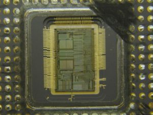
Recover PIC MCU Microchip 16LF506 Firmware and copy program to new Microcontroller PIC16LF506, clone master PIC16LF506 mcu which can provide the same functions as original master Microprocessor
Data memory is composed of registers or bytes of RAM. Therefore, data memory for a device is specified by its register file. The register file is divided into two functional groups: Special Function Registers (SFR) and General Purpose Registers (GPR).
The Special Function Registers include the TMR0 register, the Program Counter (PCL), the STATUS register, the I/O registers (ports) and the File Select Register (FSR). In addition, Special Function Registers are used to control the I/O port configuration and prescaler options when Recover IC STM32F107RCT6 code.
The General Purpose Registers are used for data and control information under command of the instructions. For the PIC12F510, the register file is composed of 10 Special Function Registers, 6 General Purpose.
Registers and 32 General Purpose Registers accessed For the PIC16F506, the register file is composed of 13 Special Function Registers, 3 General Purpose Registers and 64 General Purpose Registers accessed.
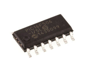
unlock microcontroller PIC16F506 tamper resistance system and extract embedded program data from flash memory
The Special Function Registers (SFRs) are registers used by the CPU and peripheral functions to control the operation of the device (see Table 4-1).
The Special Function Registers can be classified into two sets. The Special Function Registers associated with the “core” functions are described in this section for the purpose of chip AT89S8252 flash content copying.
Those related to the operation of the peripheral features are described in the section for each peripheral feature.
This register contains the arithmetic status of the ALU, the Reset status and the page preselect bit.
The STATUS register can be the destination for any instruction, as with any other register. If the STATUS register is the destination for an instruction that affects the Z, DC or C bits, then the write to these three bits is disabled. These bits are set or cleared according to the device logic. Furthermore, the TO and PD bits are not writable. Therefore, the result of an instruction with the STATUS register as destination may be different than intended.
For example, CLRF STATUS, will clear the upper three bits and set the Z bit. This leaves the STATUS register
as 000u u1uu (where u = unchanged).
Therefore, it is recommended that only BCF, BSF and MOVWF instructions be used to alter the STATUS register. These instructions do not affect the Z, DC or C bits from the STATUS register. For other instructions which do affect Status bits.
