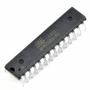
Archive for the ‘Recover Chip’ Category
 Locked AVR Chip ATMEGA64A Heximal Duplication
Locked AVR Chip ATMEGA64A Heximal Duplication means original microcontroller atmega64a will be unlocked and embedded firmware of opened atmega64a microprocessor flash memory will be readout;
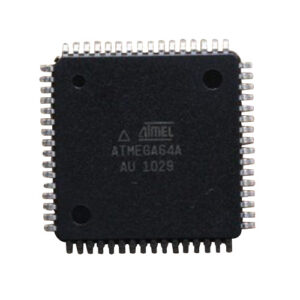
Locked AVR Chip ATMEGA64A Heximal Duplication means original microcontroller atmega64a will be unlocked and embedded firmware of opened atmega64a microprocessor flash memory will be readout
When the SM2..0 bits are written to 010, the SLEEP instruction makes the MCU enter Power- down mode. In this mode, the External Oscillator is stopped, while the external interrupts, the Two-wire Serial Interface address watch, and the Watchdog continue operating (if enabled).
Only an External Reset, a Watchdog Reset, a Brown-out Reset, a Two-wire Serial Interface address match interrupt, or an external level interrupt on INT0 or INT1, can wake up the MCU. This sleep mode basically halts all generated clocks, allowing operation of asynchronous mod- ules only.
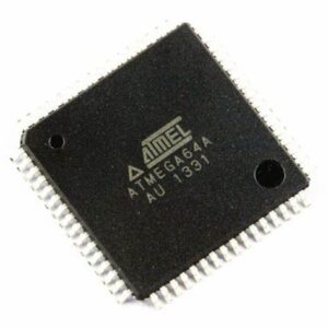
bloqueado chip AVR ATMEGA64A duplicación heximal significa microcontrolador original atmega64a será desbloqueado y el firmware incrustado de la memoria flash del microprocesador atmega64a abierto será readout;
Note that if a level triggered interrupt is used for wake-up from Power-down mode, the changed level must be held for some time to wake up the MCU. Refer to “External Interrupts” on page 66 for details of breaking off avr atmega64a flash memory binary program.
When waking up from Power-down mode, there is a delay from the wake-up condition occurs until the wake-up becomes effective. This allows the clock to restart and become stable after having been stopped. The wake-up period is defined by the same CKSEL Fuses that define the Reset Time-out period, as described in “Clock Sources” on page 26.
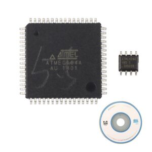
reverse atmega64a avr microcontroller protection and clone atmega64a avr mcu flash and eeprom memory data
When the SM2..0 bits are written to 011, the SLEEP instruction makes the MCU enter Power- save mode. This mode is identical to Power-down, with one exception:
If Timer/Counter2 is clocked asynchronously, that is, the AS2 bit in ASSR is set, Timer/Counter2 will run during sleep. The device can wake up from either Timer Overflow or Output Compare event from Timer/Counter2 if the corresponding Timer/Counter2 interrupt enable bits are set in TIMSK in the process of decrypting microcontroller atmega64a memory data, and the global interrupt enable bit in SREG is set.
 Deciphering AVR MCU ATmega8A Heximal Data
Deciphering AVR MCU ATmega8A Heximal Data from its flash memory needs to decode microprocessor atmega8a security fuse bit then read software file out from atmega8a microcontroller flash memory;
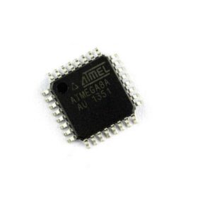
Deciphering AVR MCU ATmega8A Heximal Data from its flash memory needs to decode microprocessor atmega8a security fuse bit then read software file out from atmega8a microcontroller flash memory
Features
· High-performance, Low-power AVR® 8-bit Microcontroller
· Advanced RISC Architecture
– 130 Powerful Instructions – Most Single-clock Cycle Execution
– 32 x 8 General Purpose Working Registers
– Fully Static Operation
– Up to 16 MIPS Throughput at 16 MHz
– On-chip 2-cycle Multiplier
High Endurance Non-volatile Memory segments
– 8K Bytes of In-System Self-programmable Flash program memory
– 512 Bytes EEPROM
– 1K Byte Internal SRAM
– Write/Erase Cycles: 10,000 Flash/100,000 EEPROM
– Data retention: 20 years at 85°C/100 years at 25°C(1)
– Optional Boot Code Section with Independent Lock Bits
· In-System Programming by On-chip Boot Program
· True Read-While-Write Operation
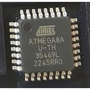
Расшифровка шестнадцатеричных данных AVR MCU ATmega8A из его флэш-памяти требует декодирования бита безопасности микропроцессора atmega8a, а затем считывания файла программного обеспечения из флэш-памяти микроконтроллера atmega8a.
8-bit with 8K Bytes In-System Programmable
– Programming Lock for Software Security
Peripheral Features
– Two 8-bit Timer/Counters with Separate Prescaler, one Compare Mode
– One 16-bit Timer/Counter with Separate Prescaler, Compare Mode, and Capture Mode
– Real Time Counter with Separate Oscillator
– Three PWM Channels
– 8-channel ADC in TQFP and QFN/MLF package
· Eight Channels 10-bit Accuracy
– 6-channel ADC in PDIP package
· Six Channels 10-bit Accuracy
– Byte-oriented Two-wire Serial Interface
– Programmable Serial USART
– Master/Slave SPI Serial Interface
– Programmable Watchdog Timer with Separate On-chip Oscillator
– On-chip Analog Comparator
Special Microcontroller Features
– Power-on Reset and Programmable Brown-out Detection
– Internal Calibrated RC Oscillator
– External and Internal Interrupt Sources
– Five Sleep Modes: Idle, ADC Noise Reduction, Power-save, Power-down, and Standby
I/O and Packages
– 23 Programmable I/O Lines
– 28-lead PDIP, 32-lead TQFP, and 32-pad QFN/MLF
Operating Voltages
– 2.7 – 5.5V for ATmega8A
Speed Grades
– 0 – 16 MHz for ATmega8A
Power Consumption at 4 Mhz, 3V, 25°
 Clone Microchip PIC12F510 Microcontroller Flash Program
Clone Microchip PIC12F510 Microcontroller Flash Program and rewrite the heximal file to new MCU PIC12F510, the lock bit of PIC12F510 microprocessor will be unlocked and original firmware can be copied from pic12f510 MCU;
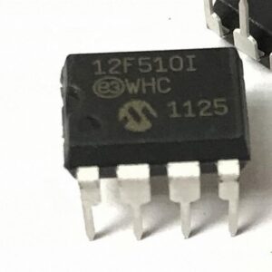
Klonuokite mikroschemą PIC12F510 mikrovaldiklio Flash programa ir perrašykite šešioliktainį failą į naują MCU PIC12F510, PIC12F510 mikroprocesoriaus blokavimo bitas bus atrakintas ir originali programinė įranga gali būti nukopijuota iš pic12f510 MCU.
An A/D conversion can be started by the “special event trigger” of the CCP1 module. This requires that the CCP1M3:CCP1M0 bits (CCP1CON<3:0>) be programmed as ‘1011’ and that the A/D module is enabled (ADON bit is set). When the trigger occurs, the GO/ DONE bit will be set, starting the A/D acquisition and conversion and the Timer1 (or Timer3) counter will be reset to zero.
Timer1 (or Timer3) is reset to auto-matically repeat the A/D acquisition period with minimal software overhead (moving ADRESH/ADRESL to the desired location). The appropriate analog input channel must be selected and the minimum acquisition period is either timed by the user to unlock pic12f510 mcu fuse bit, or an appropriate TACQ time selected before the “special event trigger” sets the GO/DONE bit (starts a conversion).
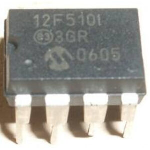
Klon Mikrochip PIC12F510 Mikrokontroller Flash Programm a schreift d’heximal Datei op den neie MCU PIC12F510, de Sperrbit vum PIC12F510 Mikroprozessor gëtt opgehuewen an d’originell Firmware kann vum pic12f510 MCU kopéiert ginn
If the A/D module is not enabled (ADON is cleared), the “special event trigger” will be ignored by the A/D module, but will still reset the Timer1 (or Timer3) counter.
x = unknown, u = unchanged, q = depends on CONFIG1H<3:0>, – = unimplemented, read as ‘0’.
Shaded cells are not used for A/D conversion.
Note 1: RA5 port bit is available only as an input pin when the MCLRE bit in the Configuration register is ‘0’.
2: RA6 and TRISA6 are available only when the primary oscillator mode selection offers RA6 as a port pin; otherwise, RA6 always reads ‘0’, TRISA6 always reads ‘1’ and writes to both are ignored (see CONFIG1H<3:0>).
3: RA7 and TRISA7 are available only when the internal RC oscillator is configured as the primary oscillator in CON- FIG1H<3:0> by cracking microcontroller pic12f510 flash memory program; otherwise, RA7 always reads ‘0’, TRISA7 always reads ‘1’ and writes to both are ignored.
 Restoring Texas Instrument TMS320F2806PZA MCU Flash OUT File
Restoring Texas Instrument TMS320F2806PZA MCU Flash OUT File needs to unlock the protection over dsp microcontroller tms320f2806pza flash memory, and extract the firmware code out from tms320f2806pza microprocessor memory;
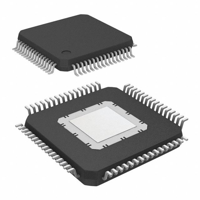
The Enhanced USART module can receive a Break character in two ways.
The first method forces configuration of the baud rate at a frequency of 9/13 the typical speed. This allows for the Stop bit transition to be at the correct sampling location (12 bits for Break versus Start bit and eight data bits for typical data).
The second method uses the auto-wake-up feature described in Section 16.3.4 “Auto-Wake-up on Sync Break Character”. By enabling this feature, the EUSART will sample the next two transitions on RX/DT, cause an RCIF interrupt and receive the next data byte followed by another interrupt.
Note that following a Break character, the user will typically want to enable the Auto-Baud Rate Detect feature. For both methods, the user can set the ABD bit before placing the EUSART in its Sleep mode to crack locked mcu tms320f28069 flash memory protection.
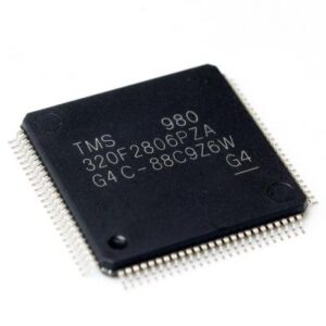
Восстановление флэш-памяти микроконтроллера Texas Instrument TMS320F2806PZA OUT Файл необходим для разблокировки защиты флэш-памяти микроконтроллера tms320f2806pza dsp и извлечения кода прошивки из памяти микропроцессора tms320f2806pza.
The following sequence will send a message frame header made up of a Break, followed by an auto-baud Sync byte. This sequence is typical of a LIN bus master.
- Configure the EUSART for the desired mode.
- Set the TXEN and SENDB bits to set up the Break character.
- Load the TXREG with a dummy character to initiate transmission (the value is ignored).
- Write ‘55h’ to TXREG to load the Sync character into the transmit FIFO buffer.
After the Break has been sent, the SENDB bit is reset by hardware. The Sync character now transmits in the preconfigured mode to break dsp controller tms320f2806pza memory. When the TXREG becomes empty, as indicated by the TXIF, the next data byte can be written to TXREG.
 Texas Instrument DSP TMS320F28069FPNT MCU Binary Restoration
Texas Instrument DSP TMS320F28069FPNT MCU Binary Restoration can be executed through cracking dsp locked microcontroller tms320f28069 fuse bit, then readout flash memory program from processor tms320f28069;

Based on the end application design and operational profile, the IDD and IDDIO currents could vary. Systems that exceed the recommended maximum power dissipation in the end product may require additional thermal enhancements. Ambient temperature (TA) varies with the end application and product design. The critical factor that affects reliability and functionality is TJ, the junction temperature, not the ambient temperature.
Hence, care should be taken to keep TJ within the specified limits. Tcase should be measured to estimate the operating junction temperature TJ. Tcase is normally measured at the center of the package top-side surface when breaking ti mcu tms320f28034png. The thermal application report Semiconductor and IC Package Thermal Metrics helps to understand the thermal metrics and definitions.
Восстановление двоичного кода микроконтроллера Texas Instrument DSP TMS320F28069FPNT может быть выполнено путем взлома заблокированного микроконтроллера tms320f28069 фьюз-бита dsp, а затем считывания программы флэш-памяти из процессора tms320f28069.
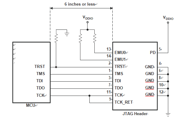
Below Figure shows the connection between the MCU and JTAG header for a single-processor configuration. If the distance between the JTAG header and the MCU is greater than 6 inches, the emulation signals must be buffered. If the distance is less than 6 inches to attack tms320f28235pg microprocessor protection system, buffering is typically not needed. Below Figure shows the simpler, no-buffering situation. For the pullup/pulldown resistor values, see Section 6.2, Signal Descriptions.
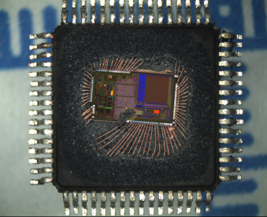
 Recover Microprocessor TMS320F2801PZA Secured Flash Binary
Recover Microprocessor TMS320F2801PZA Secured Flash Binary and clone flash memory file to new dsp microcontroller tms320f2801pza, the original memory program will be readout from tms320f2801pza processor;
The baseline IDD current (current when the core is executing a dummy loop with no peripherals enabled) is 40 mA, typical. To arrive at the IDD current for a given application, the current-drawn by the peripherals (enabled by that application) must be added to the baseline IDD current.
Following are other methods to reduce power consumption further:
The flash module may be powered down if code is run off SARAM. This results in a current reduction of 18 mA (typical) in the VDD rail and 13 mA (typical) in the VDDIO rail to attack tms320f28027 mcu archive file from its flash memory.
Savings in IDDIO may be realized by disabling the pullups on pins that assume an output function.
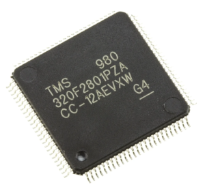
recuperar microprocesador TMS320F2801PZA asegurado binario flash y clonar archivo de memoria flash a nuevo microcontrolador dsp tms320f2801pza, el programa de memoria original será readout de procesador tms320f2801pza
To realize the lowest VDDA current consumption in a low-power mode, see the respective analog chapter of the TMS320F2803x Real-Time Microcontrollers Technical Reference Manual to ensure each module is powered down as well.
These values are based on a JEDEC defined 2S2P system (with the exception of the Theta JC [RΘJC] value, which is based on a JEDEC defined 1S0P system) and will change based on environment as well as application to . For more information, see these EIA/JEDEC standards:
JESD51-2, Integrated Circuits Thermal Test Method Environmental Conditions – Natural Convection (Still Air) by break ic tms320f28044 heximal from mcu;
JESD51-3, Low Effective Thermal Conductivity Test Board for Leaded Surface Mount Packages
JESD51-7, High Effective Thermal Conductivity Test Board for Leaded Surface Mount Packages
JESD51-9, Test Boards for Area Array Surface Mount Package Thermal Measurements
(2) lfm = linear feet per minute
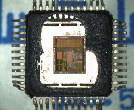
 Restore Microchip PIC18F25K50 Processor Flash Heximal
Restore Microchip PIC18F25K50 Processor Flash Heximal from its embedded flash memory, the tamper resistance system of PIC18F25K50 Microcontroller will be cracked, and then copy flash heximal from pic18f25k50 microprocessor flash memory;
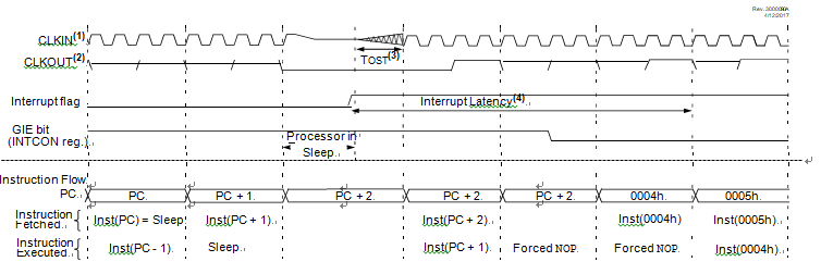
The WDT is cleared when the device wakes-up from Sleep, regardless of the source of wake-up.
Upon a wake from a Sleep event, the core will wait for a combination of three conditions before beginning execution. The conditions are:
PFM Ready
COSC-Selected Oscillator Ready
BOR Ready (unless BOR is disabled)
When global interrupts are disabled (GIE cleared) and any interrupt source, with the exception of the clock switch interrupt to break PIC18F25K20 microchip controller locked memory, has both its interrupt enable bit and interrupt flag bit set, one of the following will occur:
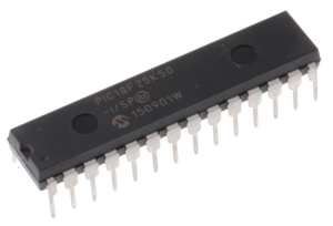
restaurar Microchip PIC18F25K50 procesador flash heximal de su memoria flash integrada, el sistema de resistencia a la manipulación de PIC18F25K50 Microcontrolador será agrietado, y luego copiar flash heximal de pic18f25k50 microprocesador de memoria flash
If the interrupt occurs before the execution of a SLEEP instruction
SLEEP instruction will execute as a NOP
Even if the flag bits were checked before executing a SLEEP instruction, it may be possible for flag bits to become set before the SLEEP instruction completes. To determine whether a SLEEP instruction executed, test the PD bit. If the PD bit is set, the SLEEP instruction was executed as a NOP.
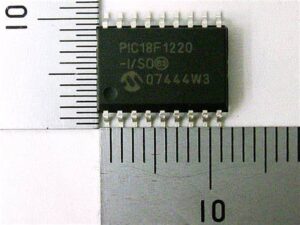
 Microchip PIC18F1220T Processor Memory Restoring
Microchip PIC18F1220T Processor Memory Restoring including cracking mcu pic18f1220t security fuse bit by focus ion beam, and then copy heximal file to new microcontroller pic18f1220t;
- Memory Endurance: The Enhanced Flash cells for both program memory and data EEPROM are rated to last for many thousands of erase/write cycles – up to 100,000 for program memory and 1,000,000 for EEPROM. Data retention without refresh is conservatively estimated to be greater than 40 years.
- Self-programmability: These devices can write to their own program memory spaces under internal software control. By using a bootloader routine located in the protected Boot Block at the top of program memory by decoding pic18f1220 microcontroller firmware, it becomes possible to create an application that can update itself in the field.
- Enhanced CCP module: In PWM mode, this module provides 1, 2 or 4 modulated outputs for controlling half-bridge and full-bridge drivers. Other features include auto-shutdown, for disabling PWM outputs on interrupt or other select conditions and auto-restart, to reactivate outputs once the condition has cleared.
- Enhanced USART: This serial communication module features automatic wake-up on Start bit and automatic baud rate detection and supports RS-232, RS-485 and LIN 1.2 protocols, making it ideally suited for use in Local Interconnect Network (LIN) bus applications.
Microchip PIC18F1220T processador de restauração de memória, incluindo rachaduras mcu pic18f1220t segurança fusível bit a feixe de íons de foco e, em seguida, copiar arquivo heximal para o novo microcontrolador pic18f1220
10-bit A/D Converter: This module incorporates programmable acquisition time, allowing for a channel to be selected and a conversion to be initiated without waiting for a sampling period and thus when extract pic18f1220 mcu source code, reduce code overhead.
 Restore R5F211A2SP IC MCU Flash Memory Data
Restore R5F211A2SP IC MCU Flash Memory Data needs to reverse engineering microcontroller r5f211a2sp locked fuse bit, readout embedded binary file from microprocessor r5f211a2sp flash memory;

The R8C/33A Group of single-chip MCUs incorporates the R8C/Tiny Series CPU core, employing sophisticated instructions for a high level of efficiency. With 1 Mbyte of address space to recover microcontroller r5f21324cnsp flash program, and it is capable of executing instructions at high speed. In addition, the CPU core boasts a multiplier for high-speed operation processing.
Power consumption is low, and the supported operating modes allow additional power control. These MCUs also use an anti-noise configuration to reduce emissions of electromagnetic noise and are designed to withstand EMI.
restaurar R5F211A2SP IC MCU dados de memória flash precisa de engenharia reversa microcontrolador r5f211a2sp bloqueado bit fusível, leitura de arquivo binário incorporado do microprocessador r5f211a2sp memória flash
Integration of many peripheral functions, including multifunction timer and serial interface, reduces the number of system components to break r5f21336tn mcu flash. The R8C/33A Group has data flash (1 KB × 4 blocks) with the background operation (BGO) function.
R8C/Tiny series core
- Number of fundamental instructions: 89
- Minimum instruction execution time:
50 ns (f(XIN) = 20 MHz, VCC = 3.0 to 5.5 V)
100 ns (f(XIN) = 10 MHz, VCC = 2.7 to 5.5 V)
200 ns (f(XIN) = 5 MHz, VCC = 2.2 to 5.5 V)
500 ns (f(XIN) = 2 MHz, VCC = 1.8 to 5.5 V)
- Multiplier: 16 bits × 16 bits ® 32 bits
- Multiply-accumulate instruction: 16 bits × 16 bits + 32 bits ® 32 bits
Operation mode: Single-chip mode (address space: 1 Mbyte)
 Protected ATmega32 MCU Eeprom Recovery
Protected ATmega32 MCU Eeprom Recovery starts from crack atmega32 microcontroller security fuse bit, and then extract source code from atmega32 mcu flash and eeprom memory;
These bits are reserved bits in the ATmega32 and will always read as zero.
The EEPROM Address Registers – EEARH and EEARL – specify the EEPROM address in the 512 bytes EEPROM space. The EEPROM data bytes are addressed linearly between 0 and 511 by pulling atmega8 mcu flash content out from its memory. The initial value of EEAR is undefined. A proper value must be written before the EEPROM may be accessed.
For the EEPROM write operation, the EEDR Register contains the data to be written to the EEPROM in the address given by the EEAR Register. For the EEPROM read operation, the EEDR contains the data read out from the EEPROM at the address given by EEAR.
Writing EERIE to one enables the EEPROM Ready Interrupt if the I bit in SREG is set. Writing EERIE to zero disables the interrupt by restoring microcontroller atmega8l flash data. The EEPROM Ready interrupt generates a constant interrupt when EEWE is cleared.
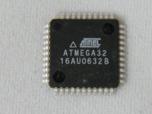
protegido ATmega32 MCU eeprom recuperação começa a partir de crack atmega32 microcontrolador de segurança fusível bit e, em seguida, extrair o código-fonte do atmega32 mcu flash e memória eeprom
The EEMWE bit determines whether setting EEWE to one causes the EEPROM to be written. When EEMWE is set, setting EEWE within four clock cycles will write data to the EEPROM at the selected address If EEMWE is zero, setting EEWE will have no effect.
When EEMWE has been written to one by software, hardware clears the bit to zero after four clock cycles. See the description of the EEWE bit for an EEPROM write procedure.
