Archive for the ‘Recover Chip’ Category
 Recover Microcontroller MSP430F4361 Flash
Recover Microcontroller MSP430F4361 Flash from Texas Instruments (TI) are 16-bit, RISC-based, mixed-signal processors designed specifically for ultra-low-power. MSP430 MCUs have the right mix of intelligent peripherals, ease-of-use, low cost and lowest power consumption for thousands of applications – including Recover Microcontroller MSP430F4361 Flash.
TI offers robust design support for the MSP430 MCU platform along with technical documents, training, tools and software to help designers develop products and release them to market faster. Learn more at www.ti.com/msp430.
Ultra-Low Power
The MSP430 MCU is designed specifically for ultra-low-power applications. Its flexible clocking system, multiple low-power modes, instant wakeup and intelligent autonomous peripherals enable true ultra-low-power optimization, dramatically extending battery life.
Flexible Clocking System – The MSP430 MCU clock system has the ability to enable and disable various clocks and oscillators which allow the device to enter various low-power modes (LPMs). The flexible clocking system optimizes overall current consumption by only enabling the required clocks when appropriate.
Multiple-Oscillator Clock System
Key Features
· Ultra-low-power (ULP) architecture and flexible clock system extend battery life: 0.1-µA RAM retention, <1-µA RTC mode,
<100 µA MHz
· Integrated intelligent peripherals including a wide range of high-performance analog and digital peripherals that off-load the CPU
· Easy-to-use 16-bit RISC CPU architecture enables new applications with industry-leading code density
· Complete development ecosystem with tools starting at $4.30
· Enhanced libraries to benefit several applications such as capacitive touch, metering metrology, low power design and debugging to Recover Microcontroller MSP430F4361 Flash.
400+ Ultra-Low-Power Devices
8-MHz to 25-MHz CPU Speed
0.5KB to 256KB Flash
128B to 18KB RAM
14 to 113 pins; 25+ packages
Sub-Main Clock (SMCLK) – Source for faster individual peripheral modules that may be driven by the internal DCO up to 25 MHz or with external crystal to Recover Microcontroller MSP430F4361 Flash.
Instant Wakeup – The MSP430 MCU can wake-up instantly from LPMs. This ultra-fast wake-up is enabled by the MSP430 MCU’s internal digitally controlled oscillator (DCO), which can source up to 25 MHz and be active and stable in 1µs. Instant wake-up functionality is important in ultra-low-power applications since it allows the microcontroller to use the CPU in very efficient bursts and spend more time in LPMs.
Zero-Power Brown-Out Reset (BOR) – The MSP430 MCU’s BOR is always enabled and active in all modes of operation.
the most reliable performance possible while maintaining ultra-low-power consumption. The BOR circuit detects low supply voltages and Lower-Power Peripherals resets the device when power is applied or removed. This functionality is especially critical in battery-power applications.
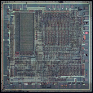
 Recover IC PIC16C74 Code
A variety of frequency ranges and packaging options are available when Recover IC PIC16C74 Code. Depending on application and production requirements, the proper device option can be selected using the information in the PIC16C7X Product Identification System section at the end of this data sheet.
When placing orders, please use that page of the data sheet to specify the correct part number.
Recover IC PIC16C74 Code
For the PIC16C7X family, there are two device “types” as indicated in the device number:
1. C, as in PIC16C74. These devices have EPROM type memory and operate over the standard voltage range.
2. LC, as in PIC16LC74. These devices have EPROM type memory and operate over an extended voltage range.
The UV erasable version, offered in CERDIP package is optimal for prototype development and pilot programs. This version can be erased and reprogrammed to any of the oscillator modes to Recover IC PIC16C74 Code. Microchip’s PICSTART® Plus and PRO MATE® II programmers both support programming of the PIC16C7X.
The OTP devices, packaged in plastic packages, permit the user to program them once. In addition to the program memory, the configuration bits must also be programmed.
Microchip offers a QTP Programming Service for factory production orders. This service is made available for users who choose not to program a medium to high quantity of units and whose code patterns have stabilized. The devices are identical to the OTP devices but with all EPROM locations and configuration options already programmed by the factory.
Microchip offers a unique programming service where a few user-defined locations in each device are programmed with different serial numbers. The serial numbers may be random, pseudo-random, or sequential. Serial programming allows each device to have a unique number which can serve as an entry-code, password, or ID number.
 Copy CPLD EPM9320ARC208-10 Binary
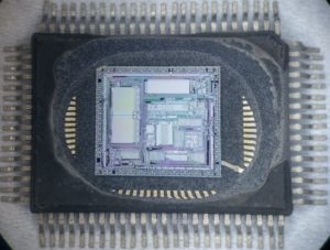
High-performance CMOS EEPROM-based programmable logic devices (PLDs) built on third-generation Multiple Array MatriX (MAX®) architecture which is the main reason for requirement on Copy CPLD EPM9320ARC208-10 Binary.
Copy CPLD EPM9320ARC208-10 Binary
5.0-V in-system programmability (ISP) through built-in IEEE Std.
1149.1 Joint Test Action Group (JTAG) interface
Built-in JTAG boundary-scan test (BST) circuitry compliant with IEEE Std. 1149.1-1990
High-density erasable programmable logic device (EPLD) family ranging from 6,000 to 12,000 usable gates (see Table 1)
10-ns pin-to-pin logic delays with counter frequencies of up to 144 MHz
Fully compliant with the peripheral component interconnect Special Interest Group’s (PCI SIG) PCI Local Bus Specification, Revision 2.2
Dual-output macrocell for independent use of combinatorial and registered logic
FastTrack® Interconnect for fast, predictable interconnect delays
Input/output registers with clear and clock enable on all I/O pins
Programmable output slew-rate control to reduce switching noise
MultiVolt™ I/O interface operation, allowing devices to interface with 3.3-V and 5.0-V devices
Configurable expander product-term distribution allowing up to 32 product terms per macrocell
Programmable power-saving mode for more than 50% power reduction in each macrocell
Programmable macrocell flipflops with individual clear, preset, clock, and clock enable controls
Programmable security bit for protection of proprietary designs which must be disable when Copy CPLD EPM9320ARC208-10 Binary
Software design support and automatic place-and-route
Altera’s MAX+PLUS® II development system on Windows-based PCs as well as Sun SPARCstation, HP 9000 Series 700/800, and IBM RISC System/6000 workstations
Additional design entry and simulation support provided by EDIF 200 and 300 netlist files, library of parameterized modules (LPM), Verilog HDL, VHDL, and other interfaces to popular EDA tools from manufacturers such as Cadence, Exemplar Logic, Mentor Graphics, OrCAD, Synopsys, Synplicity, and VeriBest
Programming support with Altera’s Master Programming Unit (MPU), BitBlasterTM serial download cable, ByteBlasterTM parallel port download cable, and ByteBlasterMVTM parallel port download cable, as well as programming hardware from third-party manufacturers.
Offered in a variety of package options with 84 to 356 pins.
 Recover Microcontroller PIC16F83 Eeprom
We can Recover Microcontroller PIC16F83 Eeprom, please view the Microcontroller PIC16F83 features for your reference:
High Performance RISC CPU Features:
• Only 35 single word instructions to learn
• All instructions single cycle except for program branches which are two-cycle Operating speed: DC – 10 MHz clock input
DC – 400 ns instruction cycle
14-bit wide instructions
8-bit wide data path
15 special function hardware registers
Eight-level deep hardware stack
Direct, indirect and relative addressing modes
Four interrupt sources:
– External RB0/INT pin
– TMR0 timer overflow
– PORTB<7:4> interrupt on change
– Data EEPROM write complete
· 1000 erase/write cycles Flash program memory
· 10,000,000 erase/write cycles EEPROM data memory
· EEPROM Data Retention > 40 years
Peripheral Features:
· 13 I/O pins with individual direction control
· High current sink/source for direct LED drive
– 25 mA sink max. per pin
– 20 mA source max. per pin
· TMR0: 8-bit timer/counter with 8-bit programmable prescaler
Special Microcontroller Features:
· In-Circuit Serial Programming (ICSP™) – via two pins (ROM devices support only Data EEPROM programming)
· Power-on Reset (POR)
· Power-up Timer (PWRT)
· Oscillator Start-up Timer (OST)
· Watchdog Timer (WDT) with its own on-Microcontroller RC oscillator for reliable operation
· Code-protection
· Power saving SLEEP mode
· Selectable oscillator options
Low-power, high-speed technology
· Fully static design
· Wide operating voltage range:
– Commercial: 2.0V to 6.0V
– Industrial: 2.0V to 6.0V
· Low power consumption:
– < 2 mA typical @ 5V, 4 MHz
– 15 µA typical @ 2V, 32 kHz
– < 1 µA typical standby current @ 2V
Circuit Engineering Company Limited continues to be recognized as the Southern China Leader in Services for IC Read, MCU Recover, Microcontroller Extract, Microcontroller Unlock service. With the advancement of today’s modern circuit board technology, it is more important than ever to have specialists available to help you at a moment’s notice. Our engineering and commercial teams collectively have a vast amount of electronic experience covering field include Consumer Electronics, Industrial Automation Electronics, Wireless Communication Electronics., etc. For more information please contact us through email.
 Recover MCU PIC16C71 Code
The PIC16C71X is a family of low-cost, high-performance, CMOS, fully-static, 8-bit microcontrollers with integrated analog-to-digital (A/D) converters, in the PIC16CXX mid-range family when it becomes necessary to Recover MCU PIC16C71 Code. All PIC16/17 microcontrollers employ an advanced RISC architecture by Break IC TS83C51U2 Binary. The PIC16CXX microcontroller family has enhanced core features, eight-level deep stack, and multiple internal and external interrupt sources.
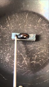
Recover MCU PIC16C71 Code
The separate instruction and data buses of the Harvard architecture allow a 14-bit wide instruction word with the separate 8-bit wide data. The two stage instruction pipeline allows all instructions to execute in a single cycle, except for program branches which require two cycles. A total of 35 instructions (reduced instruction set) are available in the process of Crack MCU Program. Additionally, a large register set gives some of the architectural innovations used to achieve a very high performance.
PIC16CXX microcontrollers typically achieve a 2:1 code compression and a 4:1 speed improvement over other 8-bit microcontrollers in their class. The PIC16C71 devices have 36 bytes of RAM, the PIC16C711 has 68 bytes of RAM and the PIC16C715 has 128 bytes of RAM. Each device has 13 I/O pins. In addition a timer/counter is available. Also a 4-channel high-speed 8-bit A/D is provided which provide support for Break IC ATMEGA32A Software.
The 8-bit resolution is ideally suited for applications requiring low-cost analog interface, e.g. thermostat control, pressure sensing, etc. The PIC16C71X family has special features to reduce external components, thus reducing cost, enhancing system reliability and reducing power consumption.
There are four oscillator options, of which the single pin RC oscillator provides a low-cost solution, the LP oscillator minimizes power consumption, XT is a standard crystal, and the HS is for High Speed crystals only in order to Recover MICROCONTROLLER ATMEGA64PA Binary. The SLEEP (power-down) feature provides a power saving mode. The user can wake up the MCU from SLEEP through several external and internal interrupts and resets.
 Recover IC PIC16C554 Software
We can Recover IC PIC16C554 Software, please view the Ic PIC16C554 features for your reference:
High Performance RISC CPU:
· Only 35 instructions to learn
· All single-cycle instructions (200 ns), except for program branches which are two-cycle
· Operating speed:
– DC – 20 MHz clock input
– DC – 200 ns instruction cycle
16 special function hardware registers
Special Ic Features (cont’d)
8-level deep hardware stack
Direct, Indirect and Relative addressing modes by Break MCU ATMEGA64PA Binary,
Programmable code protection
Power saving SLEEP mode
Peripheral Features:
· 13 I/O pins with individual direction control
· High current sink/source for direct LED drive Selectable oscillator options Serial in-circuit programming (via two pins) Four user programmable ID locations
· Timer0: 8-bit timer/counter with 8-bit programmable prescaler
Special Ic Features:
· Power-on Reset (POR)
· Power-up Timer (PWRT) and Oscillator Start-up Timer (OST)
· Watchdog Timer (WDT) with its own on-chip RC oscillator for reliable operation
CMOS Technology:
· Low-power, high-speed CMOS EPROM technology when Break MCU ATMEGA128PA Firmware
· Fully static design
· Wide operating voltage range
– 2.5V to 5.5V PIC16C55X
– 3.0 to 5.5V PIC16C55XA
· Commercial, industrial and extended temperature range
· Low power consumption
– < 2.0 mA @ 5.0V, 4.0 MHz
– 15 µA typical @ 3.0V, 32 kHz
– < 1.0 µA typical standby current @ 3.0V from Break IC ATMEGA128A Firmware
Circuit Engineering Company Limited continues to be recognized as the Southern China Leader in Services for IC Read, MCU Crack, MCU Recover, IC Unlock service. With the advancement of today’s modern circuit board technology, it is more important than ever to have specialists available to help you at a moment’s notice. Our engineering and commercial teams collectively have a vast amount of electronic experience covering field include Consumer Electronics, Industrial Automation Electronics, Wireless Communication Electronics., etc. For more
 Recover MCU ATmega8 Flash
We can Recover MCU ATMEGA8 Flash, please see below MCU ATMEGA8 features for your reference:
Features
· High-performance, Low-power AVR® 8-bit Microcontroller
· Advanced RISC Architecture
– 130 Powerful Instructions – Most Single-clock Cycle Execution
– 32 x 8 General Purpose Working Registers
– Fully Static Operation
– Up to 16 MIPS Throughput at 16 MHz
– On-chip 2-cycle Multiplier
Nonvolatile Program and Data Memories
– 8K Bytes of In-System Self-Programmable Flash
Endurance: 10,000 Write/Erase Cycles
– Optional Boot Code Section with Independent Lock Bits
In-System Programming by On-chip Boot Program
True Read-While-Write Operation
– 512 Bytes EEPROM
Endurance: 100,000 Write/Erase Cycles
– 1K Byte Internal SRAM
– Programming Lock for Software Security
Peripheral Features
– Two 8-bit Timer/Counters with Separate Prescaler, one Compare Mode
– One 16-bit Timer/Counter with Separate Prescaler, Compare Mode, and Capture
Mode
– Real Time Counter with Separate Oscillator
– Three PWM Channels
– 8-channel ADC in TQFP and QFN/MLF package
Eight Channels 10-bit Accuracy
– 6-channel ADC in PDIP package
Eight Channels 10-bit Accuracy
– Byte-oriented Two-wire Serial Interface
– Programmable Serial USART
– Master/Slave SPI Serial Interface
– Programmable Watchdog Timer with Separate On-chip Oscillator
– On-chip Analog Comparator
Special Microcontroller Features
– Power-on Reset and Programmable Brown-out Detection
– Internal Calibrated RC Oscillator
– External and Internal Interrupt Sources
– Five Sleep Modes: Idle, ADC Noise Reduction, Power-save, Power-down, and Standby
I/O and Packages
– 23 Programmable I/O Lines
– 28-lead PDIP, 32-lead TQFP, and 32-pad QFN/MLF
Operating Voltages
– 2.7 – 5.5V (ATmega8L)
– 4.5 – 5.5V (ATmega8)
Speed Grades
– 0 – 8 MHz (ATmega8L)
– 0 – 16 MHz (ATmega8)
Power Consumption at 4 Mhz, 3V, 25°C
 Recover Microcontroller STM32F105RCT6TR Binary
We can Recover Microcontroller STM32F105RCT6TR Binary, please view below Microcontroller STM32F105RCT6TR features for your reference:
Features
Core: ARM 32-bit Cortex™-M3 CPU
– 72 MHz maximum frequency, 1.25 DMIPS/MHz (Dhrystone 2.1) performance at 0 wait state memory
LQFP100 14 × 14 mm
LQFP64 10 × 10 mm
access
– Single-cycle multiplication and hardware division
Memories
– 64 to 256 Kbytes of Flash memory
– up to 64 Kbytes of general-purpose SRAM Clock, reset and supply management
– 2.0 to 3.6 V application supply and I/Os
– POR, PDR, and programmable voltage detector (PVD)
– 3-to-25 MHz crystal oscillator
– Internal 8 MHz factory-trimmed RC
– Internal 40 kHz RC with calibration
– 32 kHz oscillator for RTC with calibration Low power
– Sleep, Stop and Standby modes
– VBAT supply for RTC and backup registers
2 × 12-bit, 1 µs A/D converters (16 channels)
– Conversion range: 0 to 3.6 V
– Sample and hold capability
– Temperature sensor
– up to 2 MSPS in interleaved mode 2 × 12-bit D/A converters DMA: 12-channel DMA controller
– Supported peripherals: timers, ADCs, DAC, I2Ss, SPIs, I2Cs and USARTs
Up to 10 timers with pinout remap capability
– Up to four 16-bit timers, each with up to 4 IC/OC/PWM or pulse counter and quadrature (incremental) encoder input
– 1 × 16-bit motor control PWM timer with dead-time generation and emergency stop
– 2 × watchdog timers (Independent and Window)
– SysTick timer: a 24-bit downcounter
– 2 × 16-bit basic timers to drive the DAC Up to 14 communication interfaces with pinout remap capability
– Up to 2 × I2C interfaces (SMBus/PMBus)
– Up to 5 USARTs (ISO 7816 interface, LIN, IrDA capability, modem control)
– Up to 3 SPIs (18 Mbit/s), 2 with a multiplexed I2S interface that offers audio class accuracy via advanced PLL schemes
– 2 × CAN interfaces (2.0B Active) with 512 bytes of dedicated SRAM
– USB 2.0 full-speed device/host/OTG controller with on-chip PHY that supports HNP/SRP/ID with 1.25 Kbytes of dedicated SRAM
– 10/100 Ethernet MAC with dedicated DMA and SRAM (4 Kbytes): IEEE1588 hardware support, MII/RMII available on all packages
Table 1.
Device summary
– Serial wire debug (SWD) & JTAG interfaces
Reference
Part number
– Cortex-M3 Embedded Trace Macrocell™
Up to 80 fast I/O ports
– 51/80 I/Os, all mappable on 16 external interrupt vectors and almost all 5 V-tolerant CRC calculation unit, 96-bit unique ID
STM32F105xx
STM32F107xx
STM32F105R8, STM32F105V8
STM32F105RB, STM32F105VB
STM32F105RC, STM32F105VC
STM32F107RB, STM32F107VB
STM32F107RC, STM32F107VC
 Recover Chip EPM7064AETC100-4N Software
We can recover Chip EPM7064AETC100-4N software, please view below Chip EPM7064AETC100-4N features for your reference:
High-performance 3.3-V EEPROM-based programmable logic devices (PLDs) built on second-generation Multiple Array MatriX
3.3-V in-system programmability (ISP) through the built-in IEEE Std. 1149.1 Joint Test Action Group (JTAG) interface with advanced pin-locking capability
– MAX 7000AE device in-system programmability (ISP) circuitry compliant with IEEE Std. 1532
– EPM7128A and EPM7256A device ISP circuitry compatible with IEEE Std. 1532
Built-in boundary-scan test (BST) circuitry compliant with IEEE Std. 1149.1
Supports JEDEC Jam Standard Test and Programming Language (STAPL) JESD-71
Enhanced ISP features
– Enhanced ISP algorithm for faster programming (excluding EPM7128A and EPM7256A devices)
– ISP_Done bit to ensure complete programming (excluding EPM7128A and EPM7256A devices)
– Pull-up resistor on I/O pins during in-system
– Pin-compatible with the popular
4.5-ns pin-to-pin logic delays with counter frequencies of up to 227.3 MHz
MultiVoltTM I/O interface enables device core to run at 3.3 V, while I/O pins are compatible with 5.0-V, 3.3-V, and 2.5-V logic levels Pin counts ranging from 44 to 256 in a variety of thin quad flat pack (TQFP), plastic quad flat pack (PQFP), ball-grid array (BGA), space-saving FineLine BGATM, and plastic J-lead chip carrier (PLCC) packages.
Supports hot-socketing in MAX 7000AE devices
Programmable interconnect array (PIA) continuous routing structure for fast, predictable performance
PCI-compatible
Bus-friendly architecture, including programmable slew-rate control
Open-drain output option
Programmable macrocell registers with individual clear, preset, clock, and clock enable controls
Programmable power-up states for macrocell registers in MAX 7000AE devices
Programmable power-saving mode for 50% or greater power reduction in each macrocell
Configurable expander product-term distribution, allowing up to 32 product terms per macrocell
Programmable security bit for protection of proprietary designs 6 to 10 pin- or logic-driven output enable signals
Two global clock signals with optional inversion
Enhanced interconnect resources for improved routability
Fast input setup times provided by a dedicated path from I/O pin to macrocell registers
Programmable output slew-rate control
Programmable ground pins
Software design support and automatic place-and-route provided by Altera’s development systems for Windows-based PCs and Sun SPARCstation, and HP 9000 Series 700/800 workstations Additional design entry and simulation support provided by EDIF 2 0 0 and 3 0 0 netlist files, library of parameterized modules (LPM), Verilog HDL, VHDL, and other interfaces to popular EDA tools from manufacturers such as Cadence, Exemplar Logic, Mentor Graphics, OrCAD, Synopsys, Synplicity, and VeriBest
Programming support with Altera’s Master Programming Unit (MPU), MasterBlasterTM serial/universal serial bus (USB) communications cable, ByteBlasterMVTM parallel port download cable, and BitBlasterTM serial download cable, as well as programming hardware from third-party manufacturers and any JamTM STAPL File (.jam), Jam Byte-Code File (.jbc), or Serial Vector Format File- (.svf) capable in-circuit tester.
 Recover IC ATmega64L Binary
We can Recover IC ATMEGA64L Binary, please view below IC ATMEGA64L features for your reference:
· High-performance, Low-power Atmel® AVR® 8-bit Microcontroller
· Advanced RISC Architecture
– 130 Powerful Instructions – Most Single Clock Cycle Execution
– 32 x 8 General Purpose Working Registers + Peripheral Control Registers
– Fully Static Operation
– Up to 16 MIPS Throughput at 16 MHz
– On-chip 2-cycle Multiplier
High Endurance Non-volatile Memory segments
– 64 Kbytes of In-System Reprogrammable Flash program memory
– 2 Kbytes EEPROM
– 4 Kbytes Internal SRAM
– Write/Erase Cycles: 10,000 Flash/100,000 EEPROM
– Data retention: 20 years at 85°C/100 years at 25°C(1)
– Optional Boot Code Section with Independent Lock Bits
In-System Programming by On-chip Boot Program
True Read-While-Write Operation
– Up to 64 Kbytes Optional External Memory Space
– Programming Lock for Software Security
– SPI Interface for In-System Programming
JTAG (IEEE std. 1149.1 Compliant) Interface
– Boundary-scan Capabilities According to the JTAG Standard
– Extensive On-chip Debug Support
– Programming of Flash, EEPROM, Fuses, and Lock Bits through the JTAG Interface
Peripheral Features
– Two 8-bit Timer/Counters with Separate Prescalers and Compare Modes
– Two Expanded 16-bit Timer/Counters with Separate Prescaler, Compare Mode, and Capture Mode
– Real Time Counter with Separate Oscillator
– Two 8-bit PWM Channels
– 6 PWM Channels with Programmable Resolution from 1 to 16 Bits
– 8-channel, 10-bit ADC
8 Single-ended Channels
7 Differential Channels
2 Differential Channels with Programmable Gain (1x, 10x, 200x)
– Byte-oriented Two-wire Serial Interface
– Dual Programmable Serial USARTs
– Master/Slave SPI Serial Interface
– Programmable Watchdog Timer with On-chip Oscillator
– On-chip Analog Comparator
Special Microcontroller Features
– Power-on Reset and Programmable Brown-out Detection
– Internal Calibrated RC Oscillator
– External and Internal Interrupt Sources
– Six Sleep Modes: Idle, ADC Noise Reduction, Power-save, Power-down, Standby
and Extended Standby
– Software Selectable Clock Frequency
– ATmega103 Compatibility Mode Selected by a Fuse
– Global Pull-up Disable
I/O and Packages
– 53 Programmable I/O Lines
– 64-lead TQFP and 64-pad QFN/MLF
Operating Voltages
– 2.7V – 5.5V for ATmega64L
– 4.5V – 5.5V for ATmega64
Speed Grades
– 0 – 8 MHz for ATmega64L
– 0 – 16 MHz for ATmega64
