 Break Microchip PIC18F44K22 Controller Flash Memory
Break Microchip PIC18F44K22 Controller Flash Memory and crack mcu pic18f44k22 protective system then readout embedded firmware fro microcontroller;
The external Resistor-Capacitor (RC) modes support the use of an external RC circuit. This allows the designer maximum flexibility in frequency choice while keeping costs to a minimum when clock accuracy is not required. There are two modes: RC and RCIO.
In RC mode, the RC circuit connects to OSC1. OSC2/ CLKOUT outputs the RC oscillator frequency divided by 4. This signal may be used to provide a clock for external circuitry in order to faciliate the process of breaking microchip mcu pic18f14k22 flash memory, synchronization, calibration, test or other application requirements. Figure 2-8 shows the external RC mode connections.
In RCIO mode, the RC circuit is connected to OSC1. OSC2 becomes a general purpose I/O pin.
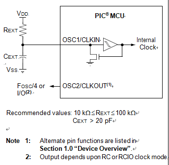
The RC oscillator frequency is a function of the supply voltage, the resistor (REXT) and capacitor (CEXT) values and the operating temperature. Other factors affecting the oscillator frequency are:
- input threshold voltage variation
- component tolerances
- packaging variations in capacitance
The user also needs to take into account variation due to tolerance of external RC components used.