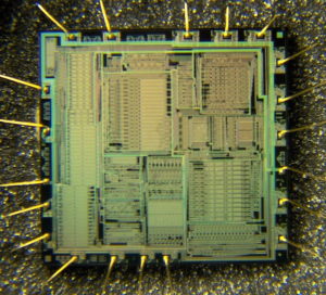
The PIC12CE518 and PIC12CE519 each have 16 bytes of EEPROM data memory which is a necessary part for Break Chip PIC12CR509A Flash. The EEPROM memory has an endurance of 1,000,000 erase/write cycles and a data retention of greater than 40 years. The EEPROM data memory supports a bi-directional 2-wire bus and data transmission protocol.
These two-wires are serial data (SDA) and serial clock (SCL), that are mapped to bit6 and bit7, respectively, of the GPIO register (SFR 06h). Unlike the GP0-GP5 that are connected to the I/O pins, SDA and SCL are only connected to the internal EEPROM peripheral. For most applications, all that is required is calls to the following functions:
The code for these functions is available on our website www.microchip.com. The code will be accessed by either including the source code FL51XINC.ASM or by linking FLASH5IX.ASM. It is very important to check the return codes when using these calls, and retry the operation if unsuccessful.
Unsuccessful return codes occur when the EE data memory is busy with the previous write, which can take up to 4 mS. SDA is a bi-directional pin used to transfer addresses and data into and data out of the device before Break chip.
For normal data transfer SDA is allowed to change only during SCL low. Changes during SCL high are reserved for indicating the START and STOP conditions. The EEPROM interface is a 2-wire bus protocol consisting of data (SDA) and a clock (SCL).
Although these lines are mapped into the GPIO register, they are not accessible as external pins; only to the i internal EEPROM peripheral. SDA and SCL operation is also slightly different than GPO-GP5 as listed below. Namely, to avoid code overhead in modifying the TRIS register, both SDA and SCL are always outputs.
To read data from the EEPROM peripheral requires outputting a ‘1’ on SDA placing it in high-Z state when Reading MCU, where only the internal 100K pull-up is active on the SDA line. SDA:
Built-in 100K (typical) pull-up to VDD Open-drain (pull-down only)
Always an output
Outputs a ‘1’ on reset
SCL:
Full CMOS output
Always an output
Outputs a ‘1’ on reset
The following example requires:
· Code Space: 77 words
· RAM Space: 5 bytes (4 are overlayable)
· Stack Levels:1 (The call to the function itself. The functions do not call any lower level functions.)
· Timing:
– WRITE_BYTE takes 328 cycles
– READ_CURRENT takes 212 cycles
– READ_RANDOM takes 416 cycles.
· IO Pins: 0 (No external IO pins are used)
This code must reside in the lower half of a page. The code achieves it’s small size without additional calls through the use of a sequencing table. The table is a list of procedures that must be called in order. The table uses an ADDWF PCL,F instruction, effectively a computed goto, to sequence to the next procedure if Break chip.
However the ADDWF PCL,F instruction yields an 8 bit address, forcing the code to reside in the first 256 addresses of a page.

