 Attack Microchip PIC18F2525 Processor Memory
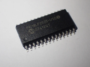
Attack Microchip PIC18F2525 processor memory can help engineer restore embedded firmware in the format of binary source code or heximal data file from secured microcontroller PIC18F2525 flash program memory and eeprom data memory, then copy/write source code to new PIC18F2525 encrypted MCU;
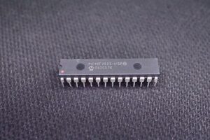
attack Microchip PIC18F2525 processor memory can help engineer restore embedded firmware in the format of binary source code or heximal data file from secured microcontroller PIC18F2525 flash program memory and eeprom data memory, then copy/write source code to new PIC18F2525 encrypted MCU;
The OSCCON register (Register 2-2) controls several aspects of the device clock’s operation which can provide critical support for Attack Microchip PIC18F2525 Processor Memory, both in full power operation and in power-managed modes to Decode Atmel AVR Processor ATMEGA169P Locked Code.
The System Clock Select bits, SCS1:SCS0, select the clock source. The available clock sources are the primary clock (defined by the FOSC3:FOSC0 Configu- ration bits), the secondary clock (Timer1 oscillator) and the internal oscillator block by Unlock Microcontroller Program. The clock source changes immediately after one or more of the bits is written to, following a brief clock transition interval. The SCS bits are cleared on all forms of Reset.
The Internal Oscillator Frequency Select bits (IRCF2:IRCF0) select the frequency output of the internal oscillator block to drive the device clock. The choices are the INTRC source, the INTOSC source (8 MHz) or one of the frequencies derived from the INTOSC postscaler for the purpose of Break Protected AVR Chip ATTINY24V Firmware (31.25 kHz to 4 MHz).
If the internal oscillator block is supplying the device clock, changing the states of these bits will have an immedi- ate change on the internal oscillator’s output. On device Resets, the default output frequency of the internal oscillator block is set at 1 MHz.
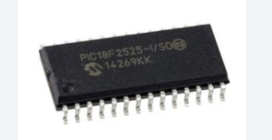
يمكن أن تساعد ذاكرة معالج PIC18F2525 من Microchip المهندس في استعادة البرامج الثابتة المضمنة بتنسيق كود المصدر الثنائي أو ملف البيانات السداسي من ذاكرة برنامج فلاش PIC18F2525 الخاصة بالميكروكنترولر المؤمنة وذاكرة بيانات EEPROM، ثم نسخ / كتابة كود المصدر إلى وحدة التحكم الدقيقة المشفرة PIC18F2525 الجديدة؛
When a nominal output frequency of 31 kHz is selected (IRCF2:IRCF0 = 000), users may choose which inter- nal oscillator acts as the source for Attack Microchip PIC18F2525 Processor Memory. This is done with the INTSRC bit in the OSCTUNE register (OSCTUNE<7>). Setting this bit selects INTOSC as a 31.25 kHz clock source by enabling the divide-by-256 output of the INTOSC postscaler.
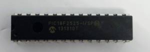
L’attacco alla memoria del processore Microchip PIC18F2525 può aiutare l’ingegnere a ripristinare il firmware incorporato nel formato di codice sorgente binario o file di dati esadecimali dalla memoria di programma flash protetta del microcontrollore PIC18F2525 e dalla memoria dati eeprom, quindi copiare/scrivere il codice sorgente sul nuovo MCU crittografato PIC18F2525;
Clearing INTSRC selects INTRC (nominally 31 kHz) as the clock source, and disables the INTOSC clock source.
This option allows users to select the tunable and more precise INTOSC as a clock source, while maintaining power savings with a very low clock speed in order to Recover ATMEL AVR ATTINY44V Flash Code. Regardless of the setting of INTSRC, INTRC always remains the clock source for features such as the Watchdog Timer and the Fail-Safe Clock Monitor.
атака Паметта на процесора Microchip PIC18F2525 може да помогне на инженера да възстанови вградения фърмуер във формат на двоичен изходен код или шестнадесетичен файл с данни от защитена флаш програмна памет PIC18F2525 на микроконтролера и памет за данни на eeprom, след което да копира/запише изходния код в нов PIC18F2525 криптиран MCU;
