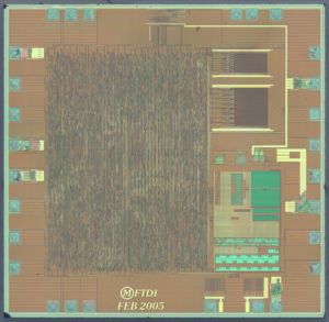
Attack Chip PIC18F66K90 starts from decapsulate the microcontroller silicon package and locate the security fuse bit which has been viewed an most commonly way to crack MCU, then extract the software out from the memory;
Low-Power Features:
· Power-Managed modes:
– Run: CPU on, peripherals on
– Idle: CPU off, peripherals on
– Sleep: CPU off, peripherals off
· Two-Speed Oscillator Start-up
· Fail-Safe Clock Monitor
· Power-Saving Peripheral Module Disable (PMD)
· Ultra Low-Power Wake-up
· Fast Wake-up, 2 ms Typical
· Low-Power WDT, 300 nA Typical
· Ultra Low 50 nA Input Leakage
· Run mode Currents Down to very low 5.5 mA, Typical
· Idle mode Currents Down to very low 2.2 mA, Typical
· Sleep mode Current Down to very low 20 nA, Typical
· RTCC Current Down to very low 700 nA, Typical
· LCD Current Down to very low 300 nA, Typical
LCD Driver and Keypad Features:
· Direct LCD Panel Drive Capability:
– Can drive LCD panel while in Sleep mode
· Up to 48 Segments and 192 Pixels, Software-Selectable
· Programmable LCD Timing module:
– Multiple LCD timing sources available
– Up to four commons: static, 1/2, 1/3 or 1/4 multiplex
– Bias configuration: Static, 1/2 or 1/3
· Low-Power Resistor Bias Network for LCD
Peripheral Highlights:
· Ten or eight CCP/ECCP modules:
– Seven Capture/Compare/PWM (CCP) modules
– Three Enhanced Capture/Compare/PWM (ECCP) modules
· Eleven 8/16-Bit Timer/Counter modules:
– Timer0 – 8/16-bit timer/counter with 8-bit programmable prescaler
– Timer1,3,5,7 – 16-bit timer/counter
– Timer2,4,6,8,10,12 – 8-bit timer/counter
· Three Analog Comparators
· Configurable Reference Clock Output
· Hardware Real-Time Clock and Calendar (RTCC) module with Clock, Calendar and Alarm Functions
– Time-out from 0.5s to 1 year
· Charge Time Measurement Unit (CTMU)
– Capacitance measurement for mTouch™ Sensing
– Time measurement with 1 ns typical resolution
· High-Current Sink/Source 25 mA/25 mA (PORTB and PORTC)
· Up to Four External Interrupts
· Two Master Synchronous Serial Port (MSSP) modules:
– 3/4-wire SPI (supports all four SPI modes)
– I2C™ Master and Slave mode
Special Microcontroller Features:
· Priority Levels for Interrupts
Operating Voltage Range: 1.8V to 5.5V
On-Chip 3.3V Regulator
Operating Speed up to 64 MHz
Up to 128 Kbytes On-Chip Flash Program Memory Data EEPROM of 1,024 Bytes
4K x 8 General Purpose Registers (SRAM)
10,000 Erase/Write Cycle Flash Program
Memory, Typical 1,000,000 Erase/write Cycle Data EEPROM
Memory, Typical Flash Retention 40 Years, Minimum
Three Internal Oscillators: LF-INTRC (31 kHz),
MF-INTOSC (500 kHz) and HF-INTOSC (16 MHz)
Self-Programmable under Software Control
· 8 x 8 Single-Cycle Hardware Multiplier
· Extended Watchdog Timer (WDT):
– Programmable period from 4 ms to 4,194s (about 70 minutes)
· In-Circuit Serial Programming™ (ICSP™) via
Two Pins
· In-Circuit Debug via Two Pins
· Programmable:
– BOR
– LVD
· Two Enhanced Addressable USART modules:
– LIN/J2602 support
– Auto-Baud Detect (ABD)
· 12-Bit A/D Converter with up to 24 Channels:
– Auto-acquisition and Sleep operation
– Differential Input mode of operation

