 Decrypt Locked PIC18F1230 Microcontroller Flash Memory
Decrypt Locked PIC18F1230 Microcontroller Flash Memory and extract embedded code from mcu pic18f1230 flash memory, the binary file of pic18f1230 microprocessor will be readout directly;

Devices in the PIC18F1220/1320 family are available in 18-pin, 20-pin and 28-pin packages. A block diagram for this device family is shown in Figure 1-1. The devices are differentiated from each other only in the amount of on-chip Flash program memory when decaps microchip pic18f1320 processor flash memory (4 Kbytes for the PIC18F1220 device, 8 Kbytes for the PIC18F1320 device).

descriptografar a memória flash do microcontrolador PIC18F1230 bloqueado e extrair o código incorporado da memória flash mcu pic18f1230, o arquivo binário do microprocessador pic18f1230 será lido diretamente
The PIC18F1220 and PIC18F1320 devices can be operated in ten different oscillator modes. The user can program the Configuration bits, FOSC3:FOSC0, in Configuration Register 1H to select one of these ten modes:
- LP Low-Power Crystal
- XT Crystal/Resonator
- HS High-Speed Crystal/Resonator
- HSPLL High-Speed Crystal/Resonator
with PLL enabled
- RC External Resistor/Capacitor with
FOSC/4 output on RA6
- RCIO External Resistor/Capacitor with
I/O on RA6
- INTIO1 Internal Oscillator with FOSC/4
output on RA6 and I/O on RA7
- INTIO2 Internal Oscillator with I/O on RA6
and RA7
- EC External Clock with FOSC/4 output
ECIO External Clock with I/O on RA6
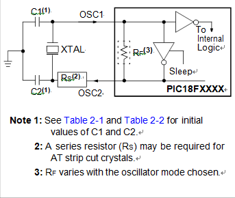
In XT, LP, HS or HSPLL Oscillator modes, a crystal or ceramic resonator is connected to the OSC1 and OSC2 pins to establish oscillation. below Figure shows the pin connections. The oscillator design requires the use of a parallel cut crystal.

RESONATOR OPERATION (XT, LP, HS OR HSPLL CONFIGURATION)