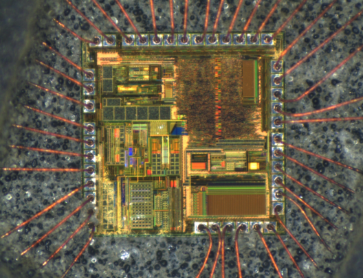
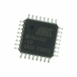
 Attack ATMEGA32U2-MU Microprocessor Fuse Bit
Attack ATMEGA32U2-MU Microprocessor Fuse Bit and unlock secured atmega32u2 processor protection over its embedded flash memory heximal, and then extract source code from atmega32u2 mcu;

The period of the Watchdog Oscillator is 1 µs (nominal) at 5.0V and 25°C. The frequency of the Watchdog Oscillator is voltage dependent as shown in “Electrical Characteristics – TA = -40°C to 85°C” on page 232.
The MCU will wake up if the input has the required level during this sampling or if it is held until the end of the start-up time. The start-up time is defined by the SUT Fuses as described in “System Clockand Clock Options” on page 31.
If the level is sampled twice by the Watchdog Oscillator clock but disappears before the end of the start-up time, the MCU will still wake up, but no interrupt will be generated to recover atmega32 mcu flash program and eeprom data. The required level must be held long enough for the MCU to complete the wake up to trigger the level interrupt.

Attack ATMEGA32U2-MU Microprocessor Fuse Bit and unlock secured atmega32u2 processor protection over its embedded flash memory heximal, and then extract source code from atmega32u2 mcu
The MCU Control Register contains control bits for interrupt sense control and general MCU functions. The External Interrupt 1 is activated by the external pin INT1 if the SREG I-bit and the corresponding interrupt mask in the GICR are set. The level and edges on the external INT1 pin that activate the interrupt are defined in Table 14-1.
The value on the INT1 pin is sampled before detecting edges. If edge or toggle interrupt is selected, pulses that last longer than one clock period will generate an interrupt when restoring atmega32l microprocessor memory software. Shorter pulses are not guaranteed to gener- ate an interrupt. If low level interrupt is selected, the low level must be held until the completion of the currently executing instruction to generate an interrupt.