 Attack Microchip MCU PIC18F46K80 Protective Flash
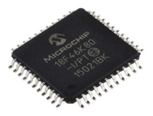
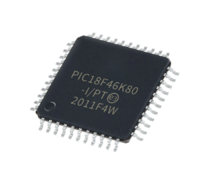
Attack Microchip MCU PIC18F46K80 Protective Flash and readout MCU embedded firmware, first of all the fuse bit of PIC18F46K80 microcontroller will be unlocked to reset the status of memory;

On boards with power traces running longer than six inches in length, it is suggested to use a tank capac- itor for integrated circuits, including microcontrollers, to supply a local power source. The value of the tank capacitor should be determined based on the trace resistance that connects the power supply source to the device, and the maximum current drawn by the device in the application.

ataque bloqueado Microchip MCU PIC18F46K80 memória flash protetora e memória eeprom para ler microcontrolador bloqueado PIC18F46K80 firmware incorporado ou código-fonte, em primeiro lugar o bit fusível de microprocessador criptografado PIC18F46K80 será recuperado para redefinir o status da memória e despejar programa binário ou arquivo heximal para fora;
In other words, select the tank capacitor so that it meets the acceptable voltage sag at the device. Typical values range from 4.7 mF to 47 mF. The MCLR pin provides two specific device functions: Device Reset, and Device Programming and Debugging which is also critical when restore pic18f44k20 microchip processor flash memory. If programming and debugging are not required in the end application, a direct connection to VDD may be all that is required.
The addition of other components, to help increase the application’s resistance to spurious Resets from voltage sags, may be beneficial. A typical configuration is shown in Figure 2-1.

атака заблокированного микроконтроллера Microchip PIC18F46K80 защитной флэш-памяти и памяти EEPROM для считывания заблокированного микроконтроллера PIC18F46K80 встроенной прошивки или исходного кода, в первую очередь бит предохранителя зашифрованного микропроцессора PIC18F46K80 будет восстановлен для сброса состояния как памяти, так и дампа двоичной программы или шестнадцатеричного файла;
Other circuit designs may be implemented, depending on the application’s requirements. During programming and debugging, the resistance and capacitance that can be added to the pin must be considered. Device programmers and debuggers drive the MCLR pin.
Consequently, specific voltage levels (VIH and VIL) and fast signal transitions must not be adversely affected. Therefore, specific values of R1 and C1 will need to be adjusted based on the application and PCB requirements.

حمله قفل شده Microchip MCU PIC18F46K80 حافظه فلش محافظ و حافظه eeprom برای بازخوانی میکروکنترلر قفل شده PIC18F46K80 سیستم عامل جاسازی شده یا کد منبع، اول از همه بیت فیوز میکروپروسسور رمزگذاری شده PIC18F46K80 بهبود خواهد یافت برای تنظیم مجدد وضعیت هر دو حافظه و تخلیه برنامه دودویی یا فایل هگزیمال؛
For example, it is recommended that the capacitor, C1, be isolated from the MCLR pin during programming and debugging operations by using a jumper (Figure 2-2). The jumper is replaced for normal run-time operations.