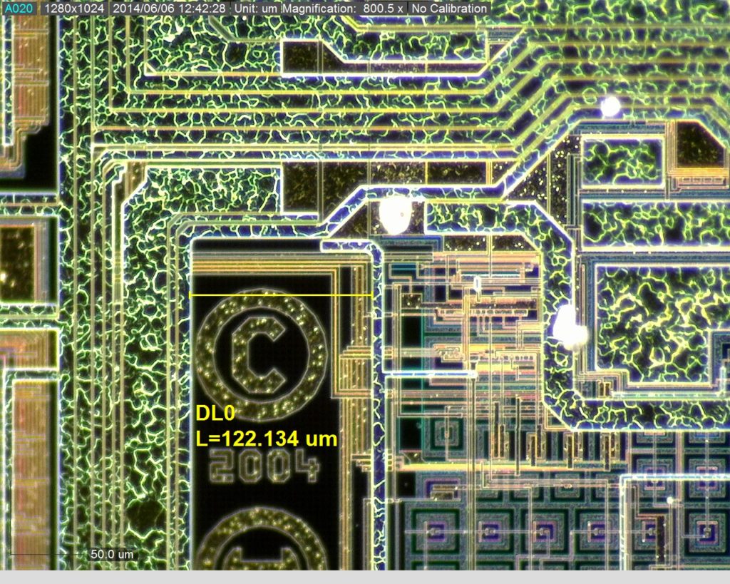
 Break IC PIC16LF74 Memory
Break IC PIC16LF74 Memory needs to cut off security fuse bit by focus ion beam and readout microcontroller PIC16LF74 progrm;

High performance RISC CPU
Only 35 single word instructions to learn
All single cycle instructions except for program branches which are two-cycle
Operating speed: DC – 20 MHz clock input DC – 200 ns instruction cycle when Break IC
Up to 8K x 14 words of FLASH Program Memory, Up to 368 x 8 bytes of Data Memory (RAM)
Pinout compatible to the PIC16LF74
Pinout compatible to the PIC16LF74
Interrupt capability (up to 12 sources)
Eight level deep hardware stack
Direct, Indirect and Relative Addressing modes
Brown-out detection circuitry for
Parallel Slave Port (PSP), 8-bits wide with Universal Synchronous Asynchronous Receiver 8-bit, up to 8-channel Analog-to-Digital converter
Synchronous Serial Port (SSP) with SPI (Master
Timer2: 8-bit timer/counter with 8-bit period
Timer0: 8-bit timer/counter with 8-bit prescaler
Timer1: 16-bit timer/counter with prescaler,
Programmable memory protection
Power saving SLEEP mode
Selectable oscillator options before Break IC
In-Circuit Serial Programming (ICSP) via two
Watchdog Timer (WDT) with its own on-chip RC
Power-on Reset (POR)
Power-up Timer (PWRT) and Processor read access to program memory Oscillator Start-up Timer (OST) oscillator for reliable operation pins can be incremented during SLEEP via external crystal/clock register, prescaler and postscaler
Two Capture, Compare, PWM modules
– Capture is 16-bit, max. resolution is 12.5 ns
– Compare is 16-bit, max. resolution is 200 ns
– PWM max. resolution is 10-bit mode) and I2C (Slave) Transmitter (USART/SCI) external RD, WR and CS controls (40/44-pin only) Brown-out Reset (BOR)
Low power, high speed CMOS FLASH technology
Fully static design
Wide operating voltage range: 2.0V to 5.5V
High Sink/Source Current: 25 mA
Industrial temperature range
Low power consumption:
– < 2 mA typical @ 5V, 4 MHz
– 20 µA typical @ 3V, 32 kHz
– < 1 µA typical standby current