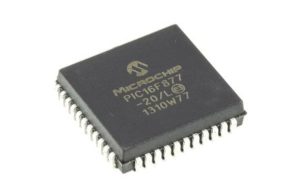
 Recover MCU PIC16F877 Heximal
The STATUS register contains the arithmetic status of the ALU, the RESET status and the bank select bits for data memory. The STATUS register can be the destination for any instruction, as with any other register which will be very helpful to Recover MCU PIC16F877 Heximal. If the STATUS register is the destination for an instruction that affects the Z, DC or C bits, then the write to these three bits is disabled. These bits are set or cleared according to the device logic.
Furthermore, the TO and PD bits are not writable, therefore, the result of an instruction with the STATUS register as destination may be different than intended.

Recover MCU PIC16F877 Heximal
The OPTION_REG Register is a readable and writable register, which contains various control bits to configure the TMR0 prescaler/WDT postscaler (single assignable register known also as the prescaler), the External INT Interrupt, TMR0 and the weak pull-ups on PORTB STAT register is the destination for an instruction that affects the Z, DC or C bits, then the write to these three bits is disabled through the process of Recover MCU 12F508 Code.
These bits are set or cleared according to the situation
RBPU: PORTB Pull-up Enable bit
1 = PORTB pull-ups are disabled
0 = PORTB pull-ups are enabled by individual port latch values
INTEDG: Interrupt Edge Select bit
1 = Interrupt on rising edge of RB0/INT pin
0 = Interrupt on falling edge of RB0/INT pin
T0CS: TMR0 Clock Source Select bit
1 = Transition on RA4/T0CKI pin
0 = Internal instruction cycle clock (CLKOUT)
T0SE: TMR0 Source Edge Select bit
1 = Increment on high-to-low transition on RA4/T0CKI pin
0 = Increment on low-to-high transition on RA4/T0CKI pin
PSA: Prescaler Assignment bit
1 = Prescaler is assigned to the WDT
0 = Prescaler is assigned to the Timer0 module
PS2:PS0: Prescaler Rate Select bits
The INTCON Register is a readable and writable register, which contains various enable and flag bits for the TMR0 register overflow, RB Port change and External RB0/INT pin interrupts.
The PIC16F87X family has an 8-level deep x 13-bit wide hardware stack. The stack space is not part of either program or data space and the stack pointer is not readable or writable. The PC is PUSHed onto the stack when a CALL instruction is executed, or an interrupt causes a branch.
The stack is POPed in the event of a RETURN,RETLW or a RETFIE instruction execution. PCLATH is not affected by a PUSH or POP operation to tamper the attempt of Microcontroller Unlocking. The stack operates as a circular buffer. This means that after the stack has been PUSHed eight times after Recover MCU PIC16F877 Heximal.
All PIC16F87X devices are capable of addressing a continuous 8K word block of program memory. The CALL and GOTO instructions provide only 11 bits of address to allow branching within any 2K program memory page. When doing aCALL or GOTO instruction after Recover Chip PIC16F83 Eeprom, the upper 2 bits of the address are provided by PCLATH<4:3>.
When doing a CALL or GOTO instruction, the user must ensure that the page select bits are programmed so that the desired program memory page is addressed. If a return from a CALL instruction (or interrupt) is executed, the entire 13-bit PC is popped off the stack.