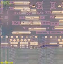
 Recover MCU ATmega644PA Flash
Recover MCU ATmega644PA Flash memory content after crack microcontroller ATmega644PA protection and extract code from microprocessor ATmega644PA memory.

When the BOD is enabled, and VCC decreases to a value below the trigger level (VBOT- in Figure 29), the Brown-out Reset is immediately activated. When VCC increases above the trigger level (VBOT+ in Figure 29), the delay counter starts the MCU after the Time- out period tTOUT has expired if recover mcu pic18f452 program.
The BOD circuit will only detect a drop in VCC if the voltage stays below the trigger level for longer than tBOD given in Table 23. When the Watchdog times out, it will generate a short reset pulse of one CK cycle duration.
On the falling edge of this pulse, the delay timer starts counting the Time-out period tTOUT. See “Watchdog Timer” on page 56. for details on operation of the Watchdog Timer after break chip pic12cr509a flash.
ATmega644PA features an internal bandgap reference. This reference is used for Brown-out Detection, and it can be used as an input to the Analog Comparator or the ADC.
The voltage reference has a start-up time that may influence the way it should be used. The start-up time is given in Table 26. To save power, the reference is not always turned The reference is on during the following situations if attack dsp mcu tms320f241pg heximal:
When the BOD is enabled (by programming the BODLEVEL [2..0] Fuse).
When the bandgap reference is connected to the Analog Comparator (by setting the ACBG bit in ACSR) before recover mcu flash. When the ADC is enabled.
Thus, when the BOD is not enabled, after setting the ACBG bit or enabling the ADC, the user must always allow the reference to start up before the output from the Analog Comparator or ADC is used.
To reduce power consumption in Power-down mode, the user can avoid the three conditions above to ensure that the reference is turned off before entering Power-down mode when recover mcu flash. ATmega644PA has an Enhanced Watchdog Timer (WDT). The main features are:
Clocked from separate On-chip Oscillator
3 Operating modes
– Interrupt
– System Reset
– Interrupt and System Reset