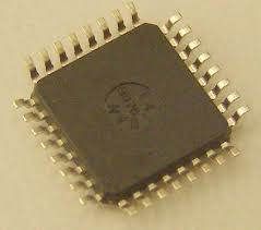
 Break PIC18F2510 Microcontroller Flash Memory
Break PIC18F2510 microcontroller flash memory protection and extract embedded firmware from secured PIC18F2510 Microchip MCU flash binary file memory and eeprom heximal data memory, copy source code to new locked microprocessor PIC18F2510;
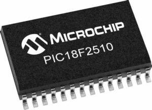
break PIC18F2510 microcontroller flash memory protection and extract embedded firmware from secured PIC18F2510 Microchip MCU flash binary file memory and eeprom heximal data memory, copy source code to new locked microprocessor PIC18F2510;
A Phase Locked Loop (PLL) circuit is provided as an option for users who wish to use a lower frequency oscillator circuit which can be used for Break PIC18F2510 Microcontroller Flash Memory, or to clock the device up to its highest rated frequency from a crystal oscillator. This may be useful for customers who are concerned with EMI due to high-frequency crystals of Protected Winbond Microprocessor W78E65 Reverse Engineering, or users who require higher clock speeds from an internal oscillator.
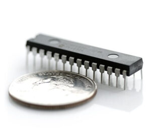
Romper la protección de la memoria flash del microcontrolador PIC18F2510 y extraer el firmware integrado de la memoria de archivo binario flash MCU Microchip PIC18F2510 protegida y la memoria de datos hexagonales EEPROM, copiar el código fuente al nuevo microprocesador PIC18F2510 bloqueado;
The HSPLL mode makes use of the HS mode oscillator for frequencies up to 10 MHz. A PLL then multiplies the oscillator output frequency by 4 to produce an internal clock frequency up to 40 MHz. The PLLEN bit is not available in this oscillator mode after Winbond MCU W78E365 Heximal Data Restoration. The PLL is only available to the crystal oscillator when the FOSC3:FOSC0 Configuration bits are programmed for HSPLL mode (= 0110).
The PLL is also available to the internal oscillator block when the INTOSC is configured as the primary clock source. In this configuration, the PLL is enabled in soft- ware and generates a clock output of up to 32 MHz. The operation of INTOSC with the PLL is described in Section 2.6.4 “PLL in INTOSC Modes” after Nuvoton Microcomputer W78E51B Encrypted Heximal Recovery.
The PIC18F2510 devices include an internal oscillator block which generates two different clock signals; either can be used as the microcontroller’s clock source. This may eliminate the need for external oscillator circuits on the OSC1 and/or OSC2 pins.
The main output (INTOSC) is an 8 MHz clock source, which can be used to directly drive the device clock. It also drives a postscaler, which can provide a range of clock frequencies from 31 kHz to 4 MHz. The INTOSC output is enabled when a clock frequency from 125 kHz to 8 MHz is selected, and can provide 31 kHz if required by Attack Nutovon Microcontroller W77E52 Flash Memory.
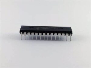
взломать защиту флэш-памяти микроконтроллера PIC18F2510 и извлечь встроенную прошивку из защищенной двоичной файловой флэш-памяти микроконтроллера PIC18F2510 Microchip и шестнадцатеричной памяти данных EEPROM, скопировать исходный код в новый заблокированный микропроцессор PIC18F2510;
The other clock source is the internal RC oscillator (INTRC) which provides a nominal 31 kHz output. INTRC is enabled if it is selected as the device clock source; it is also enabled automatically when any of the following are enabled:
• Power-up Timer
• Fail-Safe Clock Monitor
• Watchdog Timer
These features are discussed in greater detail in Section 23.0 “Special Features of the CPU” after the process of Crack MCU Eeprom. The clock source frequency (INTOSC direct, INTRC direct or INTOSC postscaler) is selected by configuring the IRCF bits of the OSCCON register on Break PIC18F2510 Microcontroller Flash Memory. Additionally, the 31 kHz clock can be provided by either the INTOSC, or INTRC clock sources, depending on the INTSRC bit (OSCTUNE<7>).
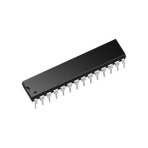
PIC18F2510 마이크로컨트롤러 플래시 메모리 보호를 해제하고 보안된 PIC18F2510 마이크로칩 MCU 플래시 바이너리 파일 메모리와 EEPROM 16진수 데이터 메모리에서 임베디드 펌웨어를 추출하고, 소스 코드를 새로운 잠긴 마이크로프로세서 PIC18F2510에 복사합니다.PIC18F2510 마이크로컨트롤러 플래시 메모리 보호를 해제하고 보안된 PIC18F2510 마이크로칩 MCU 플래시 바이너리 파일 메모리와 EEPROM 16진수 데이터 메모리에서 임베디드 펌웨어를 추출하고, 소스 코드를 새로운 잠긴 마이크로프로세서 PIC18F2510에 복사합니다.
